Scratch-Building: A Structural Perspective
Beyond the sleek lines and complicated systems that define an aircraft, lies a marvel of structural engineering—a hidden world of components designed to withstand the extraordinary forces of flight. In this article, I'll explore these essential aircraft structures and delve into how an understanding of their design fundamentally influences a successful scratch-built modelling project.
While my primary example will be the familiar Airbus A320, a modern jetliner, it's important to note that many of its underlying construction methods have been employed for decades. This means the principles discussed are applicable across a wide historical arc of aviation. For example, these insights extend even to unpressurised aircraft from an earlier era like the Avro York which was one of my past projects and more directly relevant to my latest work, the Britannia which shares significant technological commonalities with the A320's design approach, making its structural principles particularly relevant for this discussion.
Having established some basic structural definitions of real aircraft, I'll then transition to examining how these concepts translate into the practical realm of scratch-built aircraft models. While drawing inspiration from the design and construction of the actual aircraft is invaluable, the model presents its own unique set of challenges, demanding a practical and often adaptive approach to engineering its form and strength. My focus throughout will primarily be on large multi-engine monoplanes, reflecting my main modelling interest and experience over recent years.

Structural Breakdown of an Airbus A320. Source: Airbus Structural Repair Manual
Understanding the Bones: Primary and Secondary Aircraft Structures
For the dedicated modeller, replicating the sleek exterior of an aircraft is only part of the challenge; true authenticity lies in appreciating the complex engineering beneath the skin. This section explores the fundamental structural elements that define an aircraft, distinguishing between primary and secondary structures, with the familiar Airbus A320 serving as our prime example. Understanding these distinctions is not merely academic; it's crucial for achieving a structurally sound model aircraft.
Primary structures are the aircraft's backbone, absolutely essential for flight and survival in case of an emergency. These are the load-bearing components that withstand immense forces like lift, drag, thrust, and gravity throughout all phases of flight, landing, and ground operations. On an Airbus A320, these include the robust wing spars and ribs that support the entire wing and engines, the fuselage frames and longitudinal stringers that maintain the cabin's shape, critical pressure bulkheads, and finally the landing gear that bears the aircraft’s load on the ground. Note that both slats and flaps are also considered primary structures due to their crucial role in sustaining controlled flight.
In contrast, secondary structures serve important, yet non-primary load-bearing roles. While they contribute to the aircraft's overall integrity and function, they primarily focus on aerodynamic shaping, system support, access, and passenger comfort. For the A320, this includes elements like various aerodynamic fairings (e.g., wing-to-fuselage fairings, gear bay doors), access panels and internal floor beams supporting the cabin to name a few.
Anatomy of Flight: Primary Aircraft Structures
This section will delve into the primary structural components that define an aircraft's integrity, focusing on the fuselage, wings, and landing gear.
The Fuselage: A Semi-Monocoque Shell
The fuselage is the aircraft's central body, serving to house the cockpit, crew, passengers, cargo, and often connecting the wings and tail. Modern airliners like the Airbus A320 predominantly utilise a semi-monocoque construction. In this highly efficient design, the external skin carries a significant portion of the flight loads, working in concert with an internal framework. This framework consists of frames (circumferential rings that provide shape and rigidity), and stringers (longitudinal members running the length of the fuselage, reinforcing the skin against bending and compression loads). Together, the stressed skin, frames, and stringers form a remarkably strong yet lightweight structure, capable of withstanding the substantial forces of pressurisation, bending, and torsion encountered during flight.
The Wings: The Foundation of Lift and Flight Loads
Aircraft wings are engineered to generate the lift necessary for flight and to house crucial systems such as fuel tanks and landing gear bays. At the heart of a wing's strength are its spars. These are the primary load-bearing beams that run spanwise (from fuselage to wingtip) within the wing structure. Wings typically employ one or more spars (e.g., front and rear spars), which are designed to carry the vast majority of the bending loads (from lift in flight and weight on the ground) and shear forces. Supporting these spars are ribs (which define the wing's airfoil shape and provide rigidity) and stringers (which stiffen the skin and help distribute loads), all working together with the stressed skin to form the robust wing structure.
The Fuselage-to-Wing Interface: A Critical Juncture
While the fuselage and wings are distinct structures, their connection point is arguably the most critical structural junction on any aircraft. This fuselage-to-wing interface is where the enormous lift and bending loads generated by the wings are efficiently transferred into the fuselage, which then distributes them throughout the rest of the airframe. Conversely, the weight of the fuselage, passengers, and cargo must also be effectively supported by the wings through this same joint.
This connection is not simply a bolted union; it is a meticulously engineered "carry-through" structure designed for immense strength, fatigue resistance, and load distribution. Typically, the main wing spars, which are the primary load-bearing members of the wing, do not simply end at the fuselage skin. Instead, they are robustly connected to highly reinforced fuselage frames, or even extend continuously through a central wing box integrated into the fuselage structure itself. On an aircraft like the Airbus A320, the wing box forms part of the fuselage's pressurised section, making its structural integrity paramount. Specialised fittings, heavy-duty shear webs, and precision-machined tension and compression members are employed to ensure a seamless and incredibly strong transfer of forces between these two vital components, preventing stress concentrations and ensuring the aircraft's long-term durability. Understanding this complex load path is fundamental to appreciating the sophistication of aircraft design.
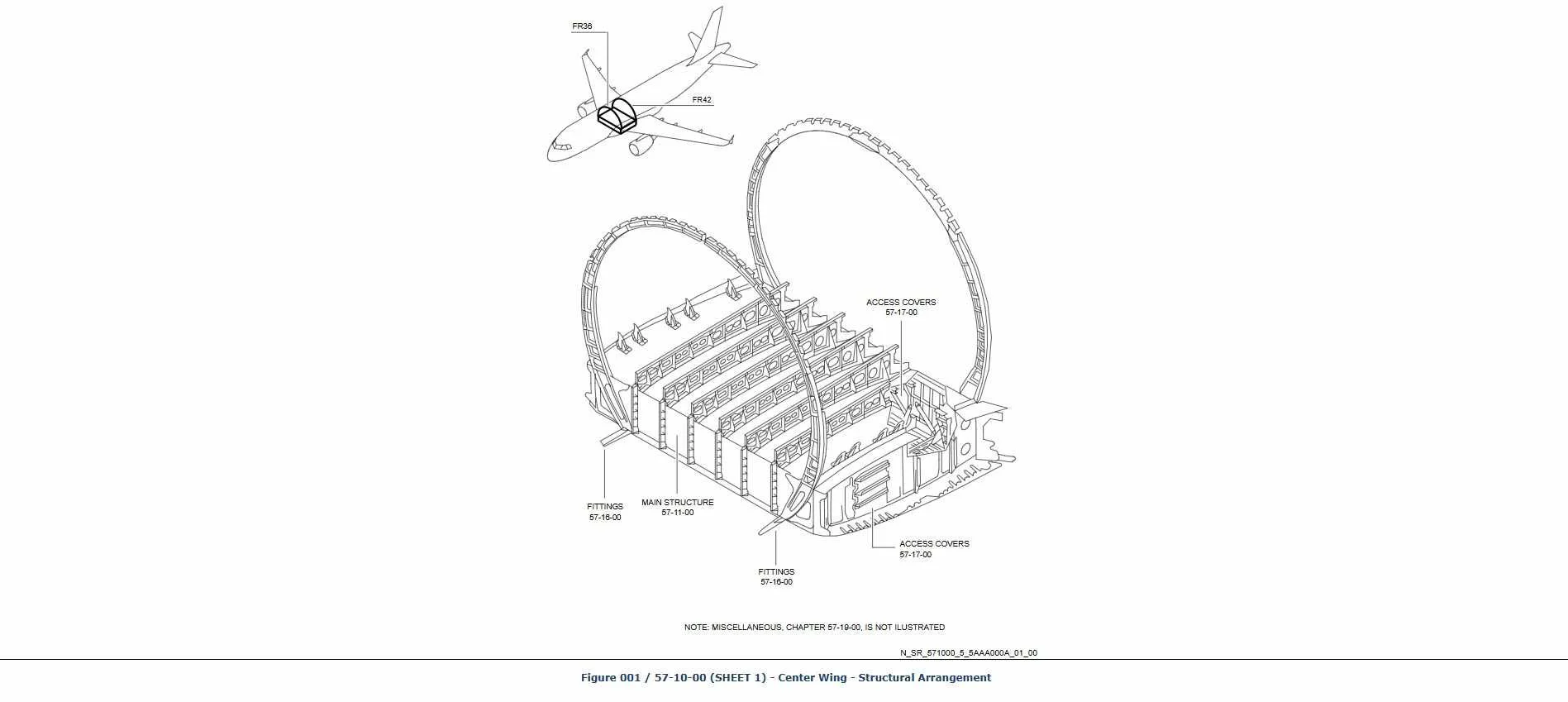
Airbus A320 Centre Wing Box with front & rear spars and fuselage frames. Source: Airbus Structural Repair Manual
The Landing Gear: Ground Support and Impact Absorption
Often overlooked, the landing gear is a highly specialised and critical structural system. Its primary role is to support the entire weight of the aircraft on the ground, provide stability during taxiing, takeoff, and landing, and most importantly, absorb the massive impact loads experienced during touchdown.
On an aircraft like the Airbus A320, the landing gear consists of the sturdy primary structural legs, oleo-pneumatic shock absorbers (which use oil and compressed gas to dampen vertical forces), wheels and tyres, and a complex arrangement of struts (drag and side), actuators, and retraction mechanisms. These components are built to endure incredible stresses, ensuring the aircraft can safely transition between air and ground.
Crucially, the main landing gear typically attaches directly to the strongest parts of the wing structure—specifically, to the main wing spars. These attachment points are heavily reinforced, often with specialised fittings and local thickening of the spar webs, to efficiently transfer the significant loads from landing impacts and ground operations directly into the wing box. For aircraft like the A320 where the main gear retracts into the wing root or an adjacent fuselage bay, these connections are engineered to handle both the static weight on the ground and the dynamic forces during retraction and extension, forming an integral part of the wing's overall structural integrity.
Translating Structure to Scale: The Model's Build
Having explored the foundational structures of real aircraft, we now shift our focus to translating these engineering marvels into the realm of scale models. This transition, while fascinating, inherently involves certain compromises in representation. After all, we're primarily using lightweight plastics to represent large, robust metal constructions, and the forces acting on a model differ significantly from those on a full-sized aircraft.
From a modelling perspective, we could define the principal airframe components as the model's Structural Platform. This platform includes the fuselage and wings, which provide the basic shape and strength, alongside the landing gear, which is critical for bearing the model's weight. To this basic structure, we then add all the integrated details and aesthetic enhancements, ranging from complex sub-assemblies to fine surface textures. Note that high lift devices such as flaps and slats as well as flight control surfaces don’t play a structural role on the model and can also be considered as integrated details.
In scratch-building, establishing a robust model's structural platform is absolutely essential. It's crucial to set up your model so it's sturdy enough to withstand handling throughout the construction process, and critically, to support its own weight once finished. This often necessitates integrating metal structures and components, which is why scratch-built models typically end up being heavier than commercially available kits.
This section of the article will systematically break down the construction of a scratch-built model into its key structural components: the fuselage, wings, wing-to-fuselage interface, and landing gear. For each component, we'll first delve into the theoretical considerations—how the principles of real aircraft design inform our modeling choices. Following this, we'll move to the practical applications, detailing the specific materials and techniques employed to faithfully represent these structures in miniature.
My approach relies on a versatile array of materials selected for their specific properties and ease of manipulation. These include various forms of plastic, such as styrene sheets for general fabrication, vacuum formed plastic for complex curves, and 3D printed ABS for more specialised applications. Metal components are indispensable for strength and fine detailing, encompassing brass, aluminium and custom photo-etched parts. Additionally, I use PU model board for shaping complex forms and Milliput superfine white epoxy putty for sculpting, filling, and finishing.
1.A. The Fuselage challenge: Theoretical Considerations
Shell Thickness vs. Robustness: One of the primary dilemmas with a model's fuselage "shell" is the inherent conflict between accommodating all interior details and ensuring the structure is robust enough not to break. While the real fuselage of an aircraft, such as an Airbus A320, might have a skin thickness of approximately 1.5mm, directly scaling down this dimension for a model is simply not viable. We must therefore make a practical compromise to safeguard the model's integrity throughout the extensive handling required during the building process and to ensure it remains durable once finished. My experience has shown that a plastic thickness of 0.7mm is the absolute minimum requirement to provide adequate inherent strength. Fortunately, for airliner models, the presence of cabin linings or insulation blankets in the real aircraft's interior allows for the model's plastic thickness to increase to a more manageable 1 to 1.5mm without compromising visual accuracy, thereby significantly enhancing structural resilience.
Fuselage Frame Shapes: Another issue to explore involves the diverse array of fuselage frame shapes, each posing its own set of modelling considerations. From the purely circular cross-sections characteristic of modern pressurized jets like the Airbus A320, designed for optimal pressure containment, to the rounded rectangles or oval shapes prevalent in most historic aircraft, which often balanced structural needs with interior space, the challenges vary. Even more complex are the compound curves found in the hulls of flying boats, demanding meticulous attention to form. Each distinct shape requires a tailored approach to construction, impacting everything from material selection to the methods used for forming and joining components.
Windows: The integration of windows often proves to be one of the most challenging aspects of fuselage construction. These elements must be transparent enough to allow visual access to interior details, yet they are remarkably sensitive to the constant sanding, filling, and general handling inevitable during the building process. Furthermore, when modeling airliners, ensuring that window rows are as identical as possible in appearance—maintaining consistent size, spacing, and alignment—is paramount for realism. While managing flat windows in certain designs is relatively straightforward, the challenges multiply significantly when dealing with the compound curves of circular fuselage shapes, demanding exceptional precision in their fabrication and installation.

A representative sample of fuselage frame shapes (Not to scale). From left to right: Avro York, Consolidated Liberator, Short Empire & Bristol Britannia
1.B. The Fuselage challenge: Practical Applications
Translating the theoretical understanding of fuselage design into a physical model requires a strategic approach to materials and construction techniques.
Curved Surfaces: When dealing with large, complex curved fuselage sections, such as those found on an airliner's nose or tail, a vacuum-formed shell can offer adequate initial structural integrity. However, for larger models, a single vacuum-formed piece often presents reduced workability, making interior detailing particularly challenging. My preferred solution for these complex forms is a modular construction method. This involves dividing the fuselage into manageable sections—typically nose, main fuselage, and tail—each acting as a separate module. This modularity significantly enhances workability, allowing for easier access to populate each section with interior details. When these fuselage sections are eventually joined, some internal reinforcement, preferably with metal but potentially with plastic, becomes necessary to ensure a strong, permanent bond. Clever solutions are often employed to discreetly hide this reinforcement behind decorative elements such as cabin linings or insulation blankets, as discussed previously. For areas within the model that feature no upholstery or paneling, photo-etched or plastic frames can be installed purely for aesthetic accuracy, though their structural contribution in the model is limited.
Cylindrical Surfaces: For the purely cylindrical sections of an airliner fuselage, the challenge lies in achieving precise diameter and perfect circularity. While various cylindrical materials like PVC pipes are commercially available, there is no guarantee that any will correspond exactly to the desired fuselage diameter for a specific scale. Therefore, 3D printing has become my preferred approach for fabricating these sections, particularly for the Britannia model. Yet again, for reasons of workability and access for interior detailing, I found it necessary to divide even these cylindrical parts into manageable sections, such as forward, mid, and aft fuselage, often split into top and bottom halves. This sectional division allows for detailing of the cabin interior before final assembly.
Flat Surfaces: Flat fuselage surfaces are generally much more straightforward to fabricate compared to their curved or cylindrical counterparts. Plain styrene sheets are often the material of choice for direct and accurate construction. In cases demanding enhanced strength or integrated precision, a sandwich construction method can be employed, combining plastic with photo-etched components. For instance, in my Empire flying boat model, this technique proved invaluable for achieving perfectly cut window openings, a common challenge discussed earlier. Similarly, the rounded rectangular fuselage frames of the Avro York were comprised of a combination of photo-etched brass frames, providing rigid internal support, and appropriately shaped styrene plastic sheets ranging from 1.0mm to 2.0mm in thickness, forming the external skin.
Fabricating Model Windows: Fabricating model windows, particularly for airliner projects, demands a high degree of precision and careful handling. For models featuring flat window panes, my preferred method involves outsourcing laser cutting of 0.5mm thick acrylic. When ordering, I instruct the cutting service to supply a couple of extra sets with slightly higher and lower tolerances. This accounts for the minute loss of material during the cutting process, ensuring that at least one version will provide a perfect fit for the photo-etched window rows incorporated into the fuselage design.
For models with curved window surfaces, I've recently begun using my Cricut Maker cutting machine with 0.3mm or less thick acetate. This material offers the significant advantage of being physically pliable enough to be bent into the curvature of the fuselage, ensuring a seamless fit. Regardless of the material or method, all windows are covered with vinyl masking film prior to installation. This crucial step protects them from accidental contact with CA (cyanoacrylate) glue during their initial placement and safeguards against scratches during their integration into the fuselage using Milliput epoxy and various grades of Mr. Surfacer.
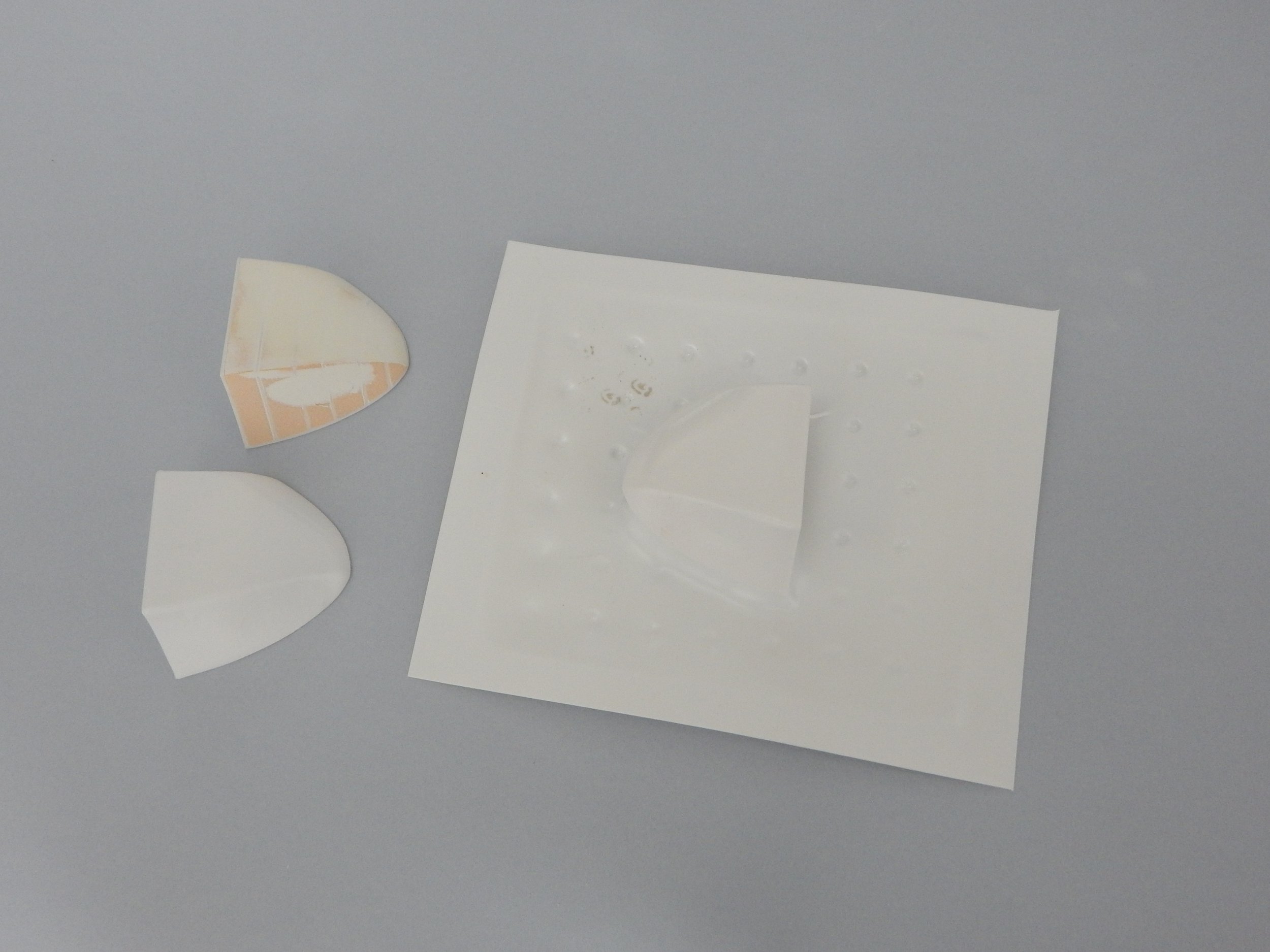
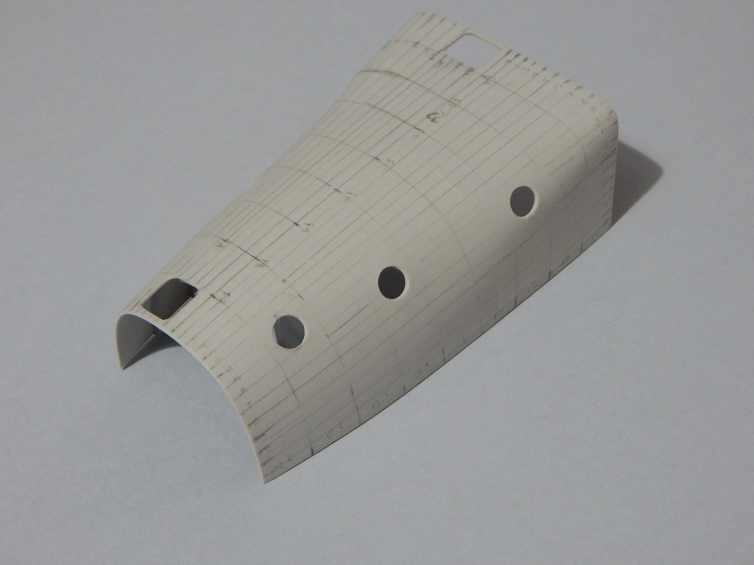
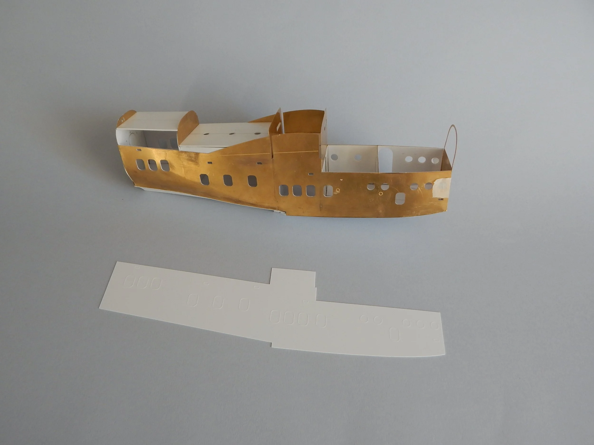
A demonstration of different applications to address the complex shape of the Empire Flying Boat. Vacuum formed nose, 3D printed forward fuselage ceiling and a sandwich construction of photo etched and plastic for the main and rather flat fuselage body.
2.A. The Wing’s Geometric Gauntlet: Theoretical Considerations
The wings are arguably the most iconic and structurally complex components of an aircraft, directly responsible for generating lift. For the scratch-builder, understanding their design is paramount.
The Airfoil's Complex Shape: At the heart of a wing's performance lies its airfoil shape. This precise cross-sectional profile is critical for aerodynamic efficiency and is usually documented in the aircraft's maintenance manuals, providing the foundational geometry for the model's wing construction. For more modern aircraft, such as the Britannia, the airfoil's shape often does not remain consistent throughout the wingspan. This phenomenon, known as aerodynamic twist or washout, involves a gradual change in the airfoil profile from the wing root (e.g., NACA 25017) to the wingtip (e.g., NACA 4413 Modified), adding a significant layer of challenge to replication. In contrast, older aircraft often employed a consistent basic airfoil across the entire span, as seen with the Empire flying boat's wing.
The Angles of Flight: Adding to the geometric frustration of airfoils, we must also meticulously consider all the angles that define a wing's position and orientation in space. These include the angle of incidence (the angle at which the wing is permanently fixed to the fuselage), sweep (the angle at which the wing is angled backward from the fuselage), dihedral or anhedral (the upward or downward angle of the wing from the horizontal), and washout (the aerodynamic twist discussed previously). Each of these angles significantly increases the challenge of accurate reproduction. A prime example is the Avro York, which features no dihedral for the inboard section of its wing, transitioning to a distinct 7 degrees of dihedral for the outboard section. All these angles profoundly affect how the wing spars—the main load-bearing elements—must be designed and built. It is truly essential to understand the entirety of a wing's three-dimensional geometry to effectively design and construct a wing from scratch.
The Tail Section: A Wing in Miniature: Even though strictly speaking the tail section belongs to the fuselage as its aft-most extremity, its construction method shares far more resemblances with that of the wings. Both the tailplane (horizontal stabiliser) and the fin (vertical stabiliser) employ specific airfoil shapes, optimised for aerodynamic stability and control. Like wings, they are typically built around a framework that includes a front and often a rear spar to provide primary structural integrity. Attached to these fixed surfaces are the movable flight control surfaces—the elevators for the horizontal tailplane and the rudder for the vertical fin—which are also designed with their own smaller airfoil sections and articulation points. Thus, many of the theoretical considerations and practical challenges encountered when building a wing apply directly to the accurate construction of the tail surfaces.
Spars as Support for Major Assemblies: Beyond their fundamental role in generating lift and carrying wing bending loads, wing spars are also critical structural members for supporting other major aircraft assemblies, notably the landing gear and engines. These attachments points are engineered to manage significant static weights and dynamic forces.
The main landing gear, for instance, is typically integrated with the wing structure at these robust spar locations. The primary loads from ground contact, taxiing, and landing impacts are usually transferred directly to the front spar, which is designed with localized reinforcements to handle these immense forces. The rear spar often provides secondary support, assisting in load distribution and contributing to the overall stability of the gear system within its bay.
Similarly, the engine mounts, or pylons, are predominantly attached to the wing's front spar. This strong forward spar is ideal for carrying the considerable weight of the powerplant and effectively transferring its thrust into the wing structure. While the front spar bears the primary burden, the rear spar may also play a crucial role in managing the overall weight and stability of the powerplant assembly, particularly in designs where engines are positioned further aft on the wing. This dual role of the spars, supporting both aerodynamic and concentrated mechanical loads, underscores their multifaceted importance in the overall aircraft structure.
2.B. The Wing’s Geometric Gauntlet: Practical Applications
Having considered the theoretical aspects of wing design, we now turn to the practical methods employed to faithfully recreate these complex structures in a scratch-built model.
Leveraging Existing Kit Wings: The first and often most time-efficient consideration for any scratch-built wing is whether a suitable wing already exists in kit form. History provides numerous examples of aircraft families sharing common wing designs due to the commercial and practical advantages for manufacturers, such as reduced development costs and the elimination of new factory construction jigs. A prime illustration is the Avro Lancaster family, where the Manchester, Lancaster, York, Lancastrian, and Lincoln aircraft all shared a largely identical wing structure. For the modeler, this means a high-quality kit wing, if available and accurate, can serve as an invaluable shortcut. This approach is something I anticipate exploring for my next large scratch-built project, involving the Boeing B-29 and Stratocruiser, which also famously share a common wing design.
Photo-Etched Frameworks for Precision: Beyond kit parts, a highly effective method for building a wing from scratch involves constructing a skeletal framework. This technique utilises a combination of photo-etched spars and airfoils (ribs) strategically placed at predetermined locations along the wing's span. Once this internal structure is assembled, it is covered with plastic sheets on both the top and bottom surfaces to form the wing skin. The leading edges, often a critical aerodynamic feature, are formed using PU model board, which is ideal for shaping compound curves. I successfully employed this technique for my Empire flying boat model, yielding highly effective and accurate results. Frustratingly enough, despite the Short Sunderland having what was essentially the exact same wing shape as the Empire (albeit with a slight sweep angle introduced due to the extra weight of the rear gun turret), the available Sanger kit had an incorrect airfoil shape and was therefore unusable as a shortcut.
The Rise of 3D Printing in Wing Construction: In recent years, to save significant time and achieve unparalleled precision, my latest approach for wing construction has shifted towards 3D printing, as demonstrated with my Britannia model. This method allows for the direct creation of the complex wing geometry, including all the aforementioned angles—incidence, sweep, dihedral, and washout—and varying airfoil profiles along the span, directly from digital design. Even with 3D printed components, my design consistently includes provision for internal metal spars to ensure the necessary structural integrity and stiffness. For the Britannia, I incorporated Albion Alloys brass square tubes into the 3D printed framework. This modern technique, combined with complex calculations to integrate all the geometric requirements into the digital design, provides a highly effective means of conquering the wing's geometric gauntlet.
Construction of the Short Empire Wing: Photo etched wing spars and aerofoils at the wing root, inboard & outboard engine centre-lines and wingtips. 1mm thick plastic was used throughout to complete the wing structure. The leading edges were primarily filled with PU model board.
3.A. Wing to Fuselage Interface: Theoretical Considerations
The Central Box Structure: At the heart of an aircraft's structural integrity lies the wing-to-fuselage interface. This is not merely a joining point, but often an integrated "box" structure that is crucial for transferring the immense forces generated by the wings into the main fuselage, and vice-versa. This complex intersection manages virtually all primary flight loads, including lift, drag, thrust, and inertia, ensuring the aircraft remains a cohesive unit under extreme conditions.
At its core, this box structure is formed by the continuation or robust connection of the wing's main spars—both front and rear—directly into, or through, the fuselage. These powerful spar elements meet and interact with equally strong, heavily reinforced fuselage frames. These specific fuselage frames, often called carry-through frames or bulkheads, are specially designed to accept and distribute the concentrated loads from the spars efficiently into the surrounding fuselage skin and stringers. This integrated approach ensures that stresses are smoothly disseminated throughout the airframe rather than creating localized stress points.
Modern aircraft, such as the Airbus A320 and even the turboprop Britannia, exemplify this sophisticated integration. They typically feature a central wing box that is often an integral part of the fuselage's pressurized section. The wing spars either pass directly through this robust box or attach to its extremely strong walls, making the transition of loads incredibly efficient. This design philosophy maximizes structural stiffness and strength-to-weight ratio.
While the specific construction methods may differ, older aircraft like the Avro York or similar mid-20th century designs, also employed a fundamental version of this principle. Though their wing attachment might have not been integrated into a pressurised cabin, the underlying concept of connecting the main wing spars to specific, strengthened fuselage cross-members remained paramount. The engineering challenge has always been, and remains, to create a seamless and robust pathway for all the forces acting on the wings to be safely absorbed and managed by the aircraft's central body.
3.B. Wing to Fuselage Interface: Practical Applications
Translating the real aircraft's sophisticated fuselage-to-wing interface into a scale model presents a unique set of practical challenges, primarily due to the combination of a hollow, relatively thin fuselage onto which the robust wings must securely attach. In most aircraft designs, the wing's main spar or spars effectively go through the fuselage, combining with corresponding reinforced fuselage frames to form a strong, integrated box structure.
For scratch-built projects, I generally rely on custom photo-etched designs for fabricating this crucial spar/frame box, tailoring the configuration to the specific type of aircraft being modelled. My approach involves a combination of both metal and plastic components. In this method, the metal provides the primary shape, strength, and rigidity required for the model's loads. The plastic, meanwhile, can take on secondary structural roles, and its ease of workability makes it ideal for integrating details and other components.
For instance, in the case of my Fw 200 Condor model, I employed this very principle. The main wing spar bulkhead was designed to integrate directly with a central fuselage frame. This primary unit was then rigidly connected to two additional bulkheads—one positioned forward and one aft—using two strong I-beams, running along both the top and bottom of the internal structure. This assembly created a highly robust, self-contained wing box within the fuselage.
A slightly different approach was taken for the Avro York. Here, I designed two distinct spar frames that served as the backbone of the wing's attachment point. These frames were then precisely joined by the wing root airfoils, ensuring correct wing incidence and dihedral. The entire assembly was further completed with thick plastic sheets, forming a sturdy central wing section. Once this core wing-fuselage platform was established, the forward and aft fuselage sections were then attached to this centrepiece, mimicking the modular construction methods often employed in real aircraft manufacturing, thereby ensuring both structural integrity and accurate representation.
Two different approaches to box structures influenced by the real aircraft unique design and the practicalities of model making. The Condor fuselage box on the left with the prominent spar frame in the middle and two bulkheads connected with metal strips (later converted to I beams). The Avro York centre box on the right was closer to the real aircraft design. Note the recesses on the wing spars for the landing gear / engine mount attachment points.
4.A. The Landing Gear’s Mechanical Marvel: Theoretical Considerations
Often overlooked when admiring an aircraft's graceful form in flight, the landing gear represents a highly interesting and remarkably complex feat of engineering. While countless designs have emerged throughout aviation history, retractable landing gears stand out as particularly fascinating from a mechanical and structural perspective. Their complex mechanisms allow heavy aircraft to transition effortlessly from solid ground to an aerodynamically clean profile in the air.
The ingenuity in retractable gear designs varies widely. Consider the Curtiss P-40 Warhawk, for example, which featured a relatively simple yet effective mechanism where the main wheels would rotate ninety degrees and retract rearward into the wing. This method allowed for a thin wing cross-section while stowing the wheel flat. In contrast, early monoplanes like the Grumman F3F Wildcat employed a rather unique hand-cranked system, where the pilot manually "wound up" the gear, leading to a complex internal mechanism that stowed the wheels into the fuselage.
As aircraft grew larger and heavier, the demands on landing gear became even more extreme, sometimes leading to configurations that, in retrospect, appear unnecessarily complicated. The Short Stirling, a British heavy bomber, for instance, had a distinctively complex main gear with multiple wheels and a unique retraction sequence, partly influenced by its design requirement to fit into specific hangar dimensions. Similarly, the Focke-Wulf Fw 200 Condor, a large German maritime patrol aircraft, also featured a multi-wheeled and somewhat convoluted main gear system, reflecting the challenges of supporting such substantial weight and absorbing significant landing impacts with the technology of its era. These diverse examples highlight the constant evolution and myriad of solutions employed to solve the fundamental challenge of safe ground operations for aircraft.
4.B. The Landing Gear’s Mechanical Marvel: Practical Applications
Translating the real aircraft landing gear into a durable and accurate model presents a unique set of challenges. The sheer variety of configurations means each type demands a tailored approach in model form. Single-leg designs are generally more straightforward to represent, but as the complexity of the gear increases—think multi-wheeled bogies or elaborate retraction mechanisms—so too does the demand for an effective design that will successfully bear the model's weight.
For the structural integrity of a model's landing gear, metal is invariably the material of choice, predominantly aluminum or brass. Telescopic Albion Alloys tubes or rods of various diameters are particularly useful for replicating the functioning struts and oleos. For my Britannia model, I've experimented with a hybrid gear combining 3D-printed components with aluminium, leveraging the strengths of both materials. In contrast, the Avro York's gear was crafted solely from aluminium tubes, which I shaped using a modelling lathe, while the Fw 200 Condor featured a brass-only construction, painstakingly assembled through soldering.
I also frequently incorporate miniature nuts and bolts to connect components. While this might deviate slightly from 100% scale accuracy in some instances, these tiny fasteners serve a crucial role in holding delicate constructions together, particularly at important joints where the strength of glue alone might be insufficient.
Wheels, too, are an important part of the landing gear's overall presentation. Replicating realistic tread patterns by hand is exceptionally difficult, but this is where the latest 3D printing technology proves to be an invaluable asset for the scratch-builder, allowing for incredibly precise detail. Alternatively, there's a wide variety of aftermarket wheels available in numerous scales, offering a convenient and high-quality solution for specific scratch-building projects. Just as aircraft wings can be common across different types to save development and manufacturing costs, wheels, and to some limited extent entire landing gear assemblies, are frequently shared components, which can sometimes provide a ready-made solution for the modeller.
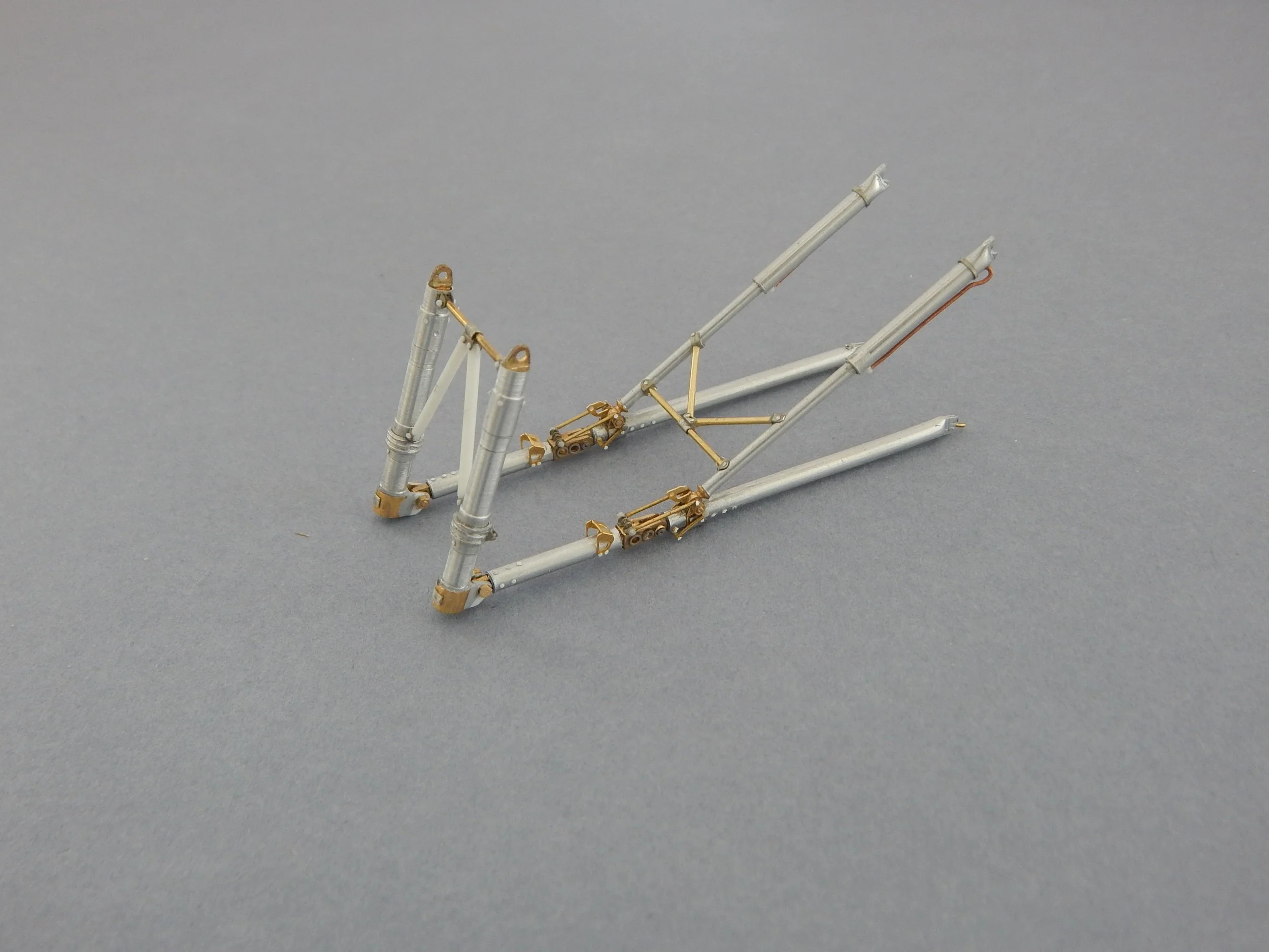
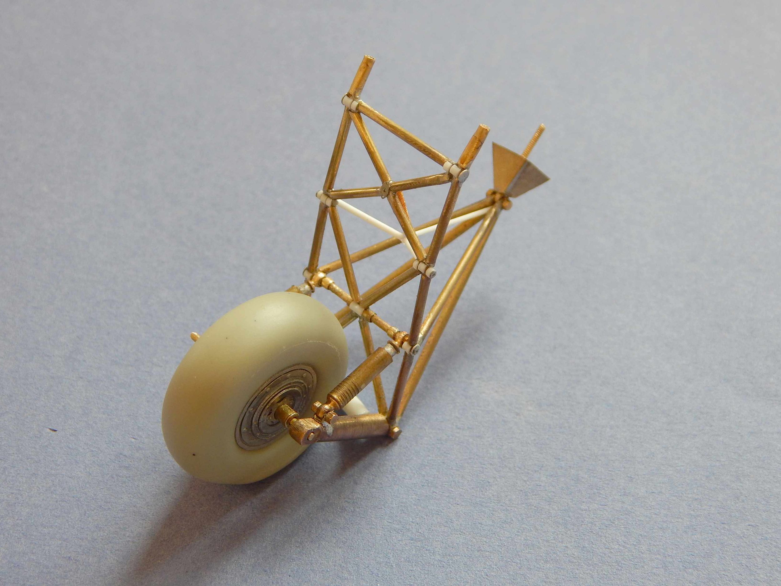

Left to right: Telescopic aluminium tubes were used to craft the single gear leg of an Airfix EE Lightning. In a similar but more complex fashion, the Avro York aluminium core also included hand-crafted as well as custom photo etched brass fittings. The geometric nightmare of the Condor landing gear was based on brass tubes, hand crafted struts and modified “Connecto” fittings. Finally the Britannia nose gear featured a hybrid 3D printed and brass rod assembly. As you can see the sky is the limit when it comes to craftsmanship and creativity!
Epilogue
While this article has primarily focused on the demands of scratch-building large, multi-engined monoplanes, the principles discussed are broadly applicable to aircraft models of varying complexity and smaller size. For instance, a single-engine World War II fighter can be scratch-built without the need for a hollow fuselage, making construction considerably simpler by employing a solid or semi-solid approach. As model size decreases, so too does the absolute need for exceptionally strong spars and landing gear, meaning plastic can often be safely used in place of more challenging metals.
Undeniably, 3D printing technology is rapidly transforming the modeling world. An increasing number of smaller companies are now offering highly exotic and previously unavailable modelling subjects, seemingly reducing the "need" for scratch-building. However, in the foreseeable future, there will still remain an array of large and complex aircraft that model manufacturers, regardless of their size, will likely shy away from, leaving ample room for the dedicated scratch-builder. Moreover, numerous examples of poorly researched and designed kits still exist, which, though claiming to represent a certain aircraft type, simply don't hit the mark for accuracy. Therefore and despite the availability of a wide variety of 3D-printed or injection-moulded kits and 3D printers and software, there is still plenty of room for the passion of creativity. In my experience, it is precisely the comprehensive process of research, design, and build that makes scratch-building such a unique and deeply interesting branch of this hobby.
