Technical Research and Model Design
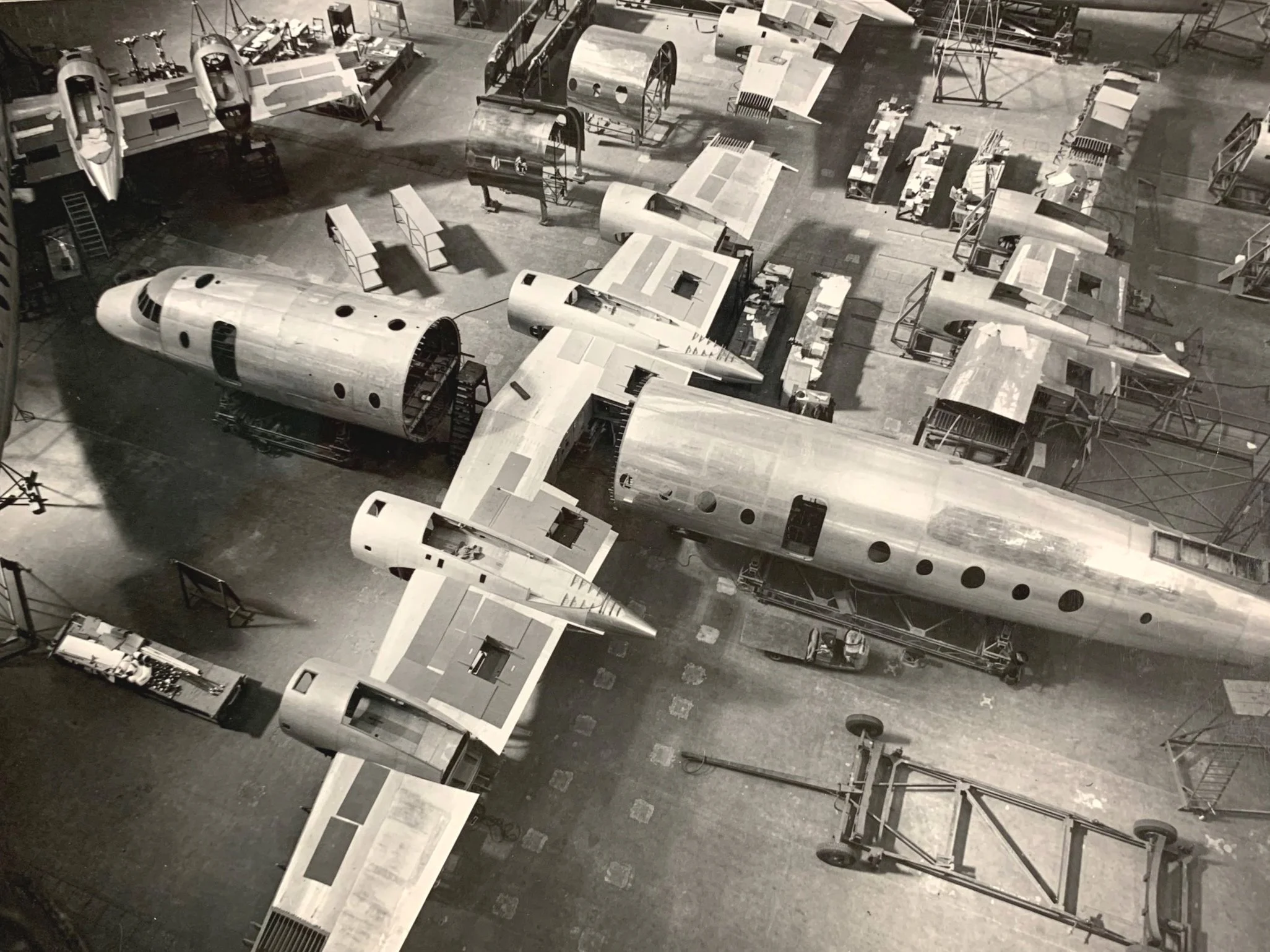
From Public Records Office Northern Ireland D4474/2/249 Image ref. T175/1371
While the internet is an invaluable research tool, it's important to remember the wealth of information available in libraries, archives, and museums. Researching the Britannia took me to locations across the UK, including Belfast (Public Record Office of Northern Ireland), Bristol (Aerospace Bristol), Farnborough (National Aerospace Library), Liverpool (Britannia Aircraft Preservation Trust), Heathrow (British Airways Heritage Collection), Imperial War Museum Duxford, and RAF Museum Cosford—a total journey of 2,032 miles (3,270 km).
Having gathered extensive information in the form of photographs, documents, books, manuals, and measurements, I faced the challenge of starting my largest and most complex model to date. After careful study of the available material, it became clear that a numerical approach would be the most effective. I began with the fuselage.
Fuselage
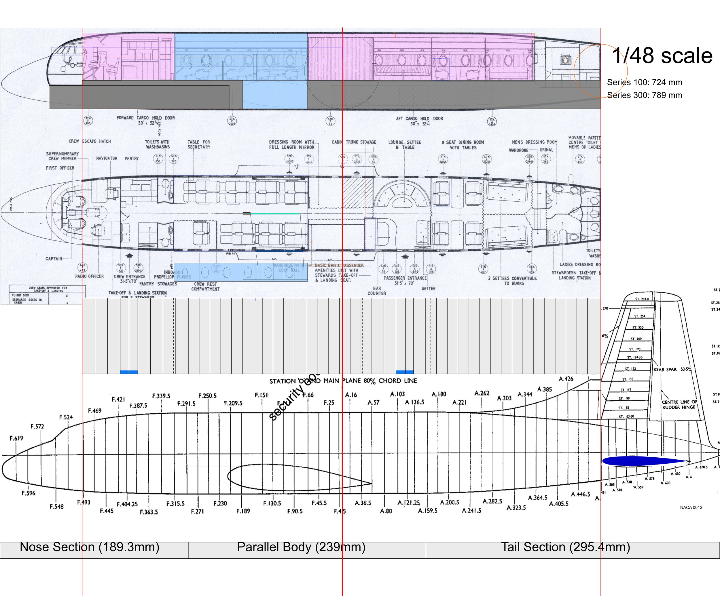
Study of fuselage frame stations with datum line in red. Light blue denotes centre section selected as basic building block for the model.
Frame station ‘0’ (the datum) for the Britannia 102 was located at the intersection of the fuselage centerline and the 80% chord line of the wing. All frame stations were actual measurements in inches, prefixed with "F" for stations forward of the datum and "A" for those aft. For example, the bulkhead at the rear of the flight deck, at station F.493, is 493 inches forward of the datum. To simplify calculations, I created a spreadsheet listing all the fuselage frame stations and divided each value by 48 (the scale factor). The spreadsheet calculations were then visualised int the form of the grey rectangle as seen in the illustration above. This way I was able to confirm the correctness of the plans I would use for the model.
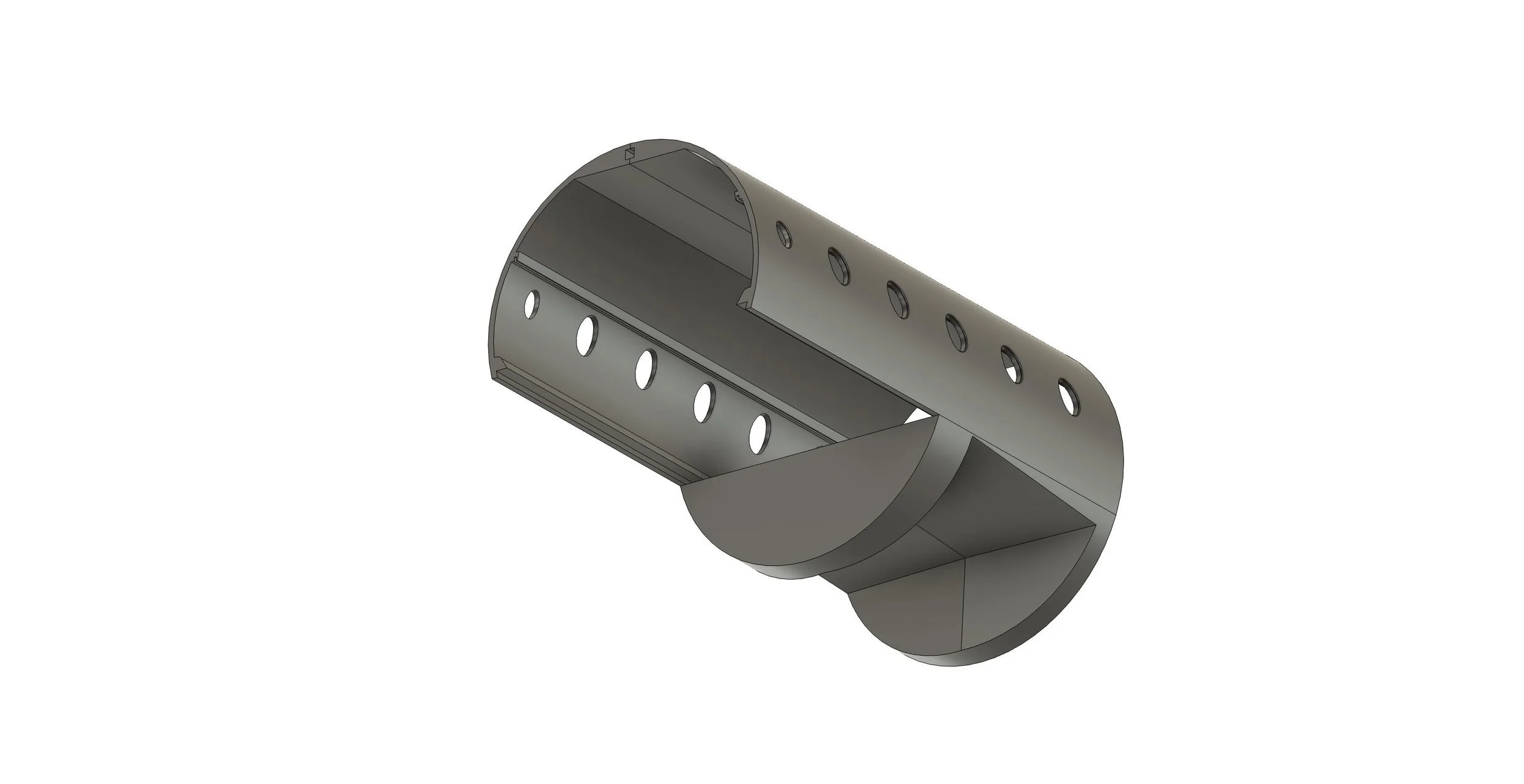
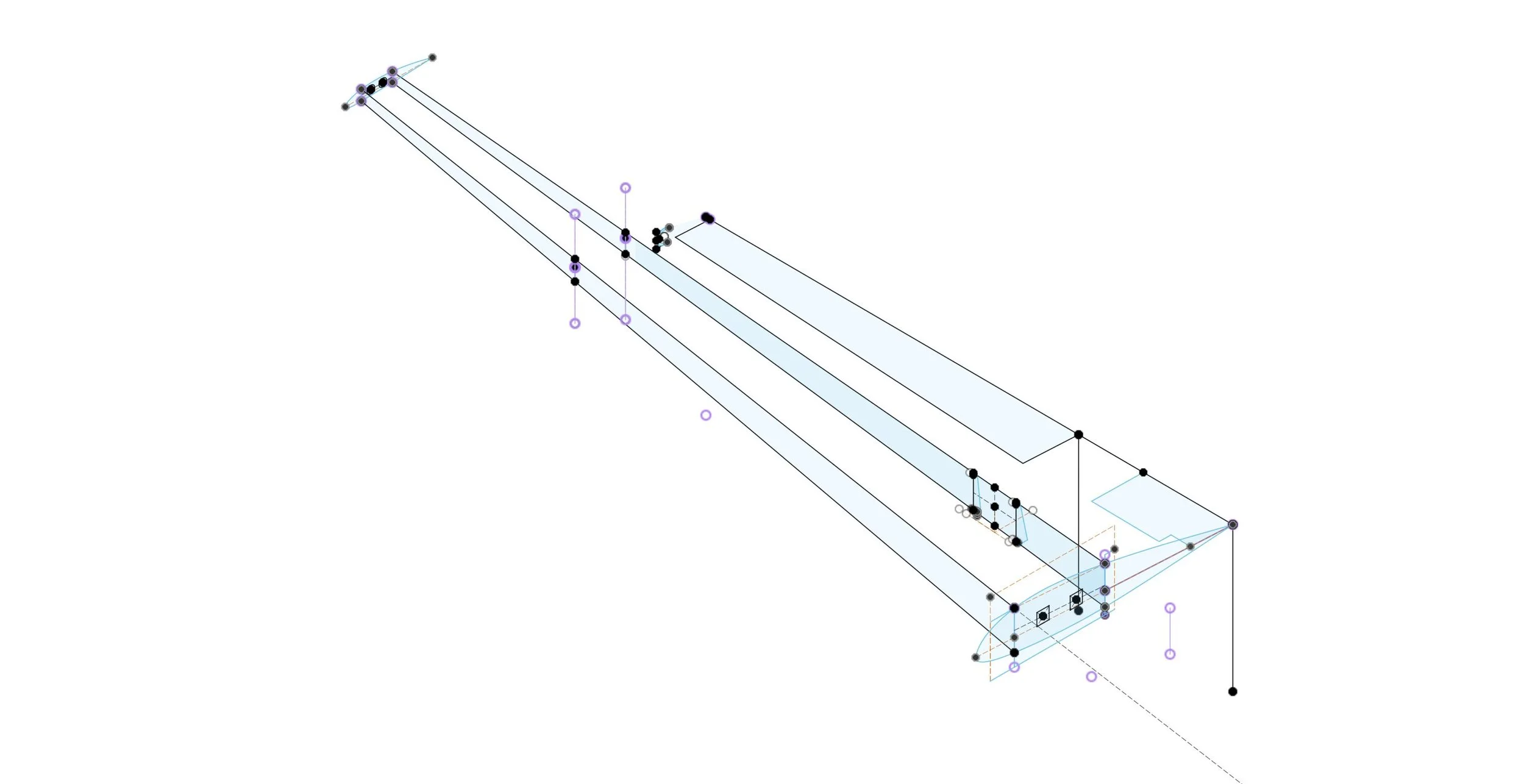
Autodesk Fusion 3D design of the model’s main component: The fuselage centre section.
The next key challenge was designing a robust yet manageable fuselage that would also accommodate interior lighting and cabin details. While the real aircraft’s manufacturing methods provided inspiration, scratch-built models are inherently different. I decided to use the cabin floor as the primary structural component, designed to slide within the upper and lower fuselage sections. Secondary support would be provided by 2mm Albion Alloys square tubes along the top. This initial design encompasses frame stations F.66 to F.320 and includes provisions for integrating the wings with the fuselage.

The Remaining fuselage as designed in Autodesk Fusion spanning from stations F493 to A491.
Every scratch-built model presents unique challenges dictated by the aircraft's design and shape. For the Britannia, the cylindrical fuselage strongly pointed towards 3D printing as the ideal construction method. Building upon the successful 3D printing trials conducted on my Empire flying boat model, I was able to significantly increase the proportion of 3D printed components in the Britannia design. However, my limitations as a designer became apparent when attempting to model the nose section. After two failed attempts I decided to resort to my vacuum forming skills. ( See blogpost on nose section)
Wings
Designing the wings was probably one of the most difficult undertakings I have ever attempted. My first major problem was that illustrations from the aircraft documentation available to me differed considerably between them and were also in some disagreement with the dimensions provided in the Maintenance Manual. I will do my best to describe this complex process as plainly as possible, and while the challenges were significant, the eventual success proved incredibly rewarding.
To be able to design the wings as accurately as possible I needed to take into account the wing’s geometry. The sweep angle (the backward slant), the dihedral angle (the upward tilt from root to tip), as well as the angle of incidence at the wing root and tip which were different because of the wing washout. Adding to the complexity were the different aerofoils – the NACA 25017 at the root, designed for higher lift, and the NACA 4413 at the tip, optimised for better control and stall characteristics.
To determine the sweep angle, I relied on Google Earth, as it offered the only overhead views of the surviving Duxford, Cosford, and Liverpool Britannias. Despite the blurry and slightly distorted images resulting from zooming in, I ultimately decided that the illustration in the maintenance manual was the closest approximation I could achieve.

The top view illustration from the Maintenance Manual corresponded more to the Google Earth Images than any of the others available. Note that the wing was the same for 100 and 300 series
Turning my attention to the dihedral and wing washout, my proximity to Duxford proved incredibly beneficial as this was the best means available to me for understanding the wing's design characteristics.
I spent several hours there, taking measurements from both wings with a laser measuring tape at the wing leading edge, front spar, rear spar, and trailing edge at predetermined frame station locations (as shown in the illustrations above and below).
I transferred this detailed information to an Excel spreadsheet, where I could analyse the changes in height and chord length along the wing. Knowing the specified NACA 25017 root aerofoil profile helped me to understand the expected dimensions and identify any deviations indicative of dihedral or washout. As it turned out, the front view in the Maintenance Manual appeared to be significantly inaccurate when compared to the physical measurements. Furthermore, my data indicated that the NACA 25017 root aerofoil maintained a consistent profile along the majority of the wing, with changes occurring only towards the tip.
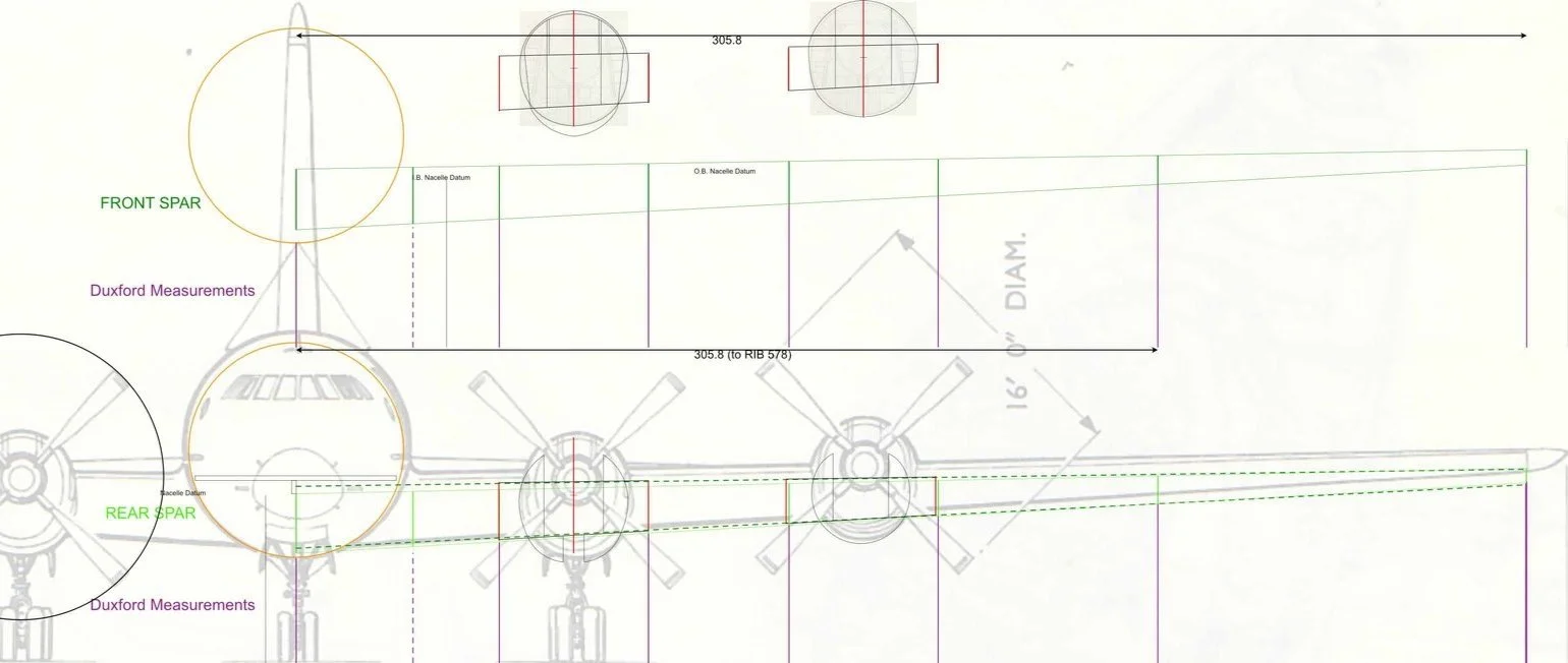
Maintenance manual front view compared to measurements from Duxford. Dark green denotes Front Spar and light green dotted line denotes Rear Spar. You will also notice a discrepancy with the fuselage.
3D Designing the wings
With the challenges of the wing design now clear, I began the process in Autodesk Fusion with somewhat limited expectations, as I needed to include a considerable amount of detailed geometric data – including the varying airfoil coordinates, sweep and dihedral angles, and washout. Given my previous struggles with the intricate design of the nose section, I approached the wing design with a degree of caution. However, determined to overcome these challenges, I rolled up my sleeves and hoped for the best.
A sample 3D sketch in Autodesk Fusion, incorporating the study made in 2D using measurements from Duxford
After considerable perseverance, and perhaps a touch of good fortune, I successfully designed the wings to meet my specifications in Fusion. I also managed to integrate the fittings for the main landing gear and incorporated openings for the flaps, which I decided to model in their extended position. Given the 90cm wingspan, I opted for a modular design, creating the wing outboard sections as separate components to be installed later along with the ailerons.

The final 3D design prior to printing. The outboard wing section and flap housing area behind the rear spar were printed separately mainly for practical reasons. Note the openings for the square Albion Alloys metal “spars” which are meant to increase the rigidity of the model’s wings even further.