Britannia Flight Deck: A Study in Detail
There's something inherently captivating about a flight deck. It’s the nerve center of a complicated flying machine, bristling with intricate dials and high-tech equipment that speaks to both control and complexity. The Bristol Britannia, a prime example from the 1950s, is no exception; its distinctive array of instruments makes it an incredibly interesting subject to model. In this article, I'll show you how I went about designing and bringing Britannia’s "office" to life.
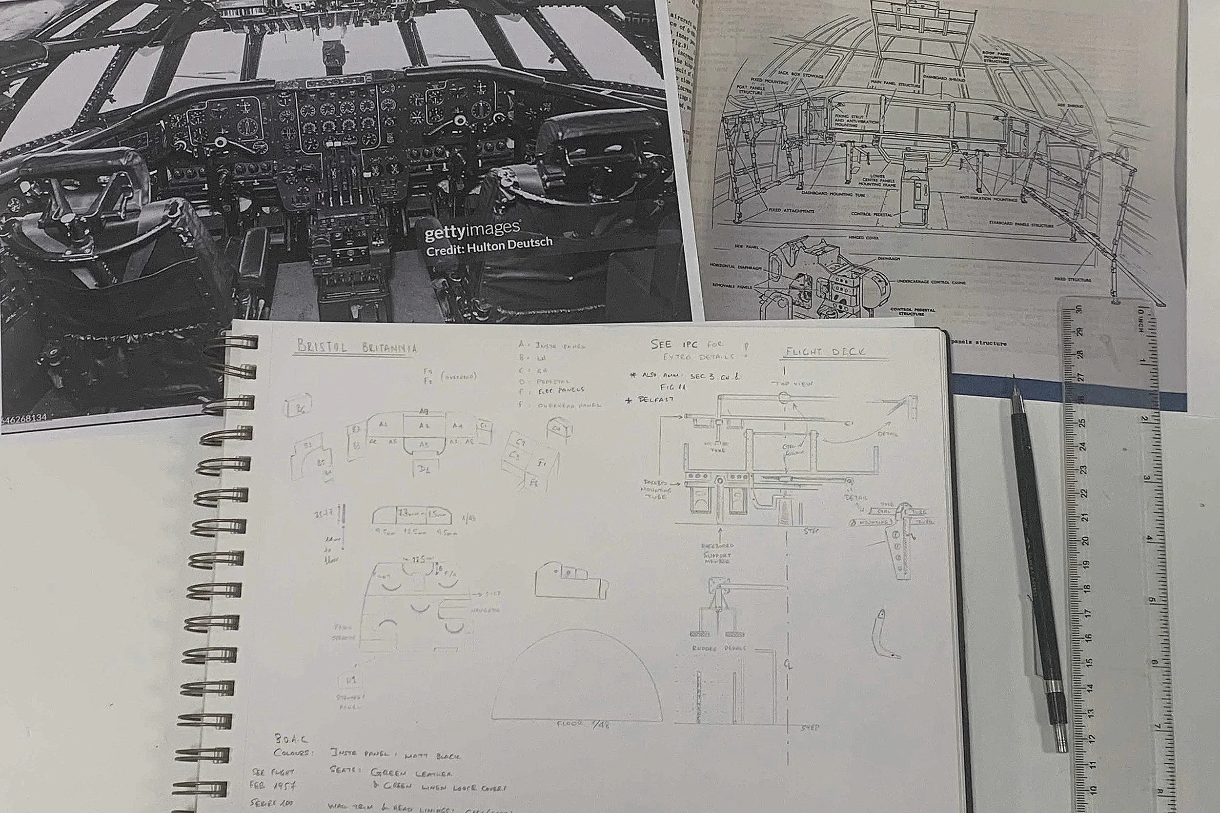
To make sense of the flight deck equipment locations and dimensions I consulted photographs and illustrations and made different sketches in a notepad. No matter how far 2D and 3D design goes, pencil and paper will always be the starting point for any creative endeavour.
The 100 Series Conundrum: Designing the Britannia's Flight Deck
As I've stressed before, thorough research and design are paramount for achieving historical and technical accuracy in modelling. And while flight deck layouts are inherently complex, my Britannia 100 series build presented an additional challenge: most available information, including details from the Duxford airframe, actually pertained to the 300 series. This significantly increased the workload of sifting through abundant data to determine which equipment was original to G-ANBG and which were later additions to the 300 series. After considerable study, I identified these differences and formulated a build plan. Given the necessary compromises and educated guesses, I'm confident the finished flight deck will be the closest possible approximation.
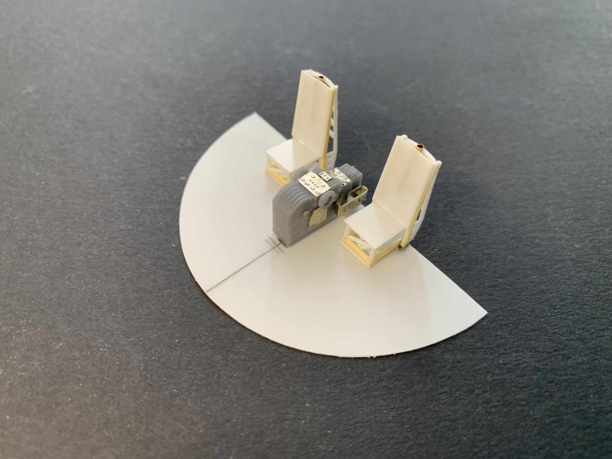
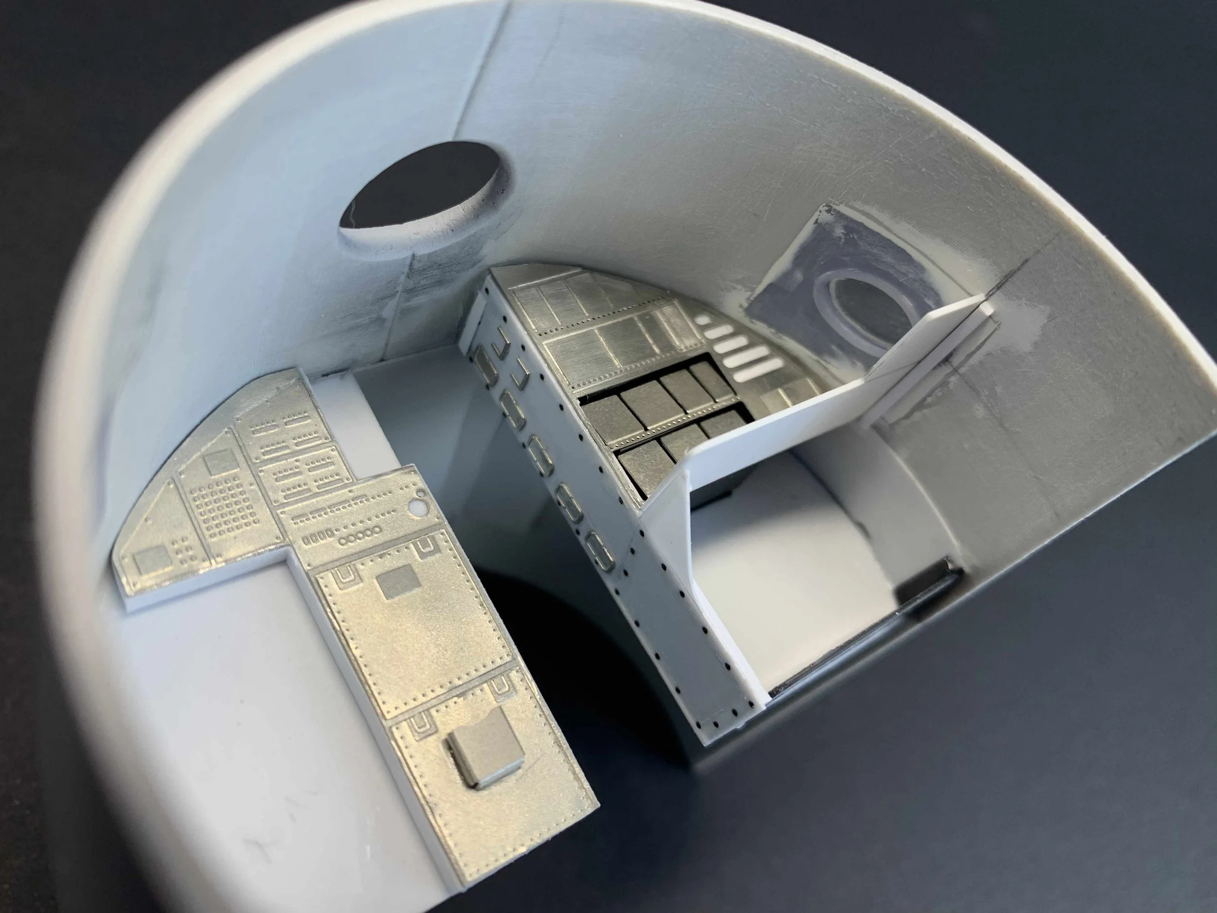
The journey into any scratch-built flight deck always begins with the floor. With a trusty pencil in hand, I carefully marked out the locations for the primary components: the instrument panel, centre pedestal, and pilot seats. Even though I'd already invested considerable time designing and having several key parts produced via photo-etching and 3D printing, I knew I still needed to effectively populate the rest of the flight deck – particularly the side consoles and other equipment – in situ.
The main reason for this flexible approach is simple: what looks perfect in a 2D design can often misbehave in the third dimension. It’s surprisingly easy to misjudge proportions or encounter fit issues when you transition from a flat drawing to a physical build. This is why, despite planning some major elements, I always leave room for improvisation and conventional scratch-building techniques. It allows me the flexibility to adapt and ensure everything fits just right.


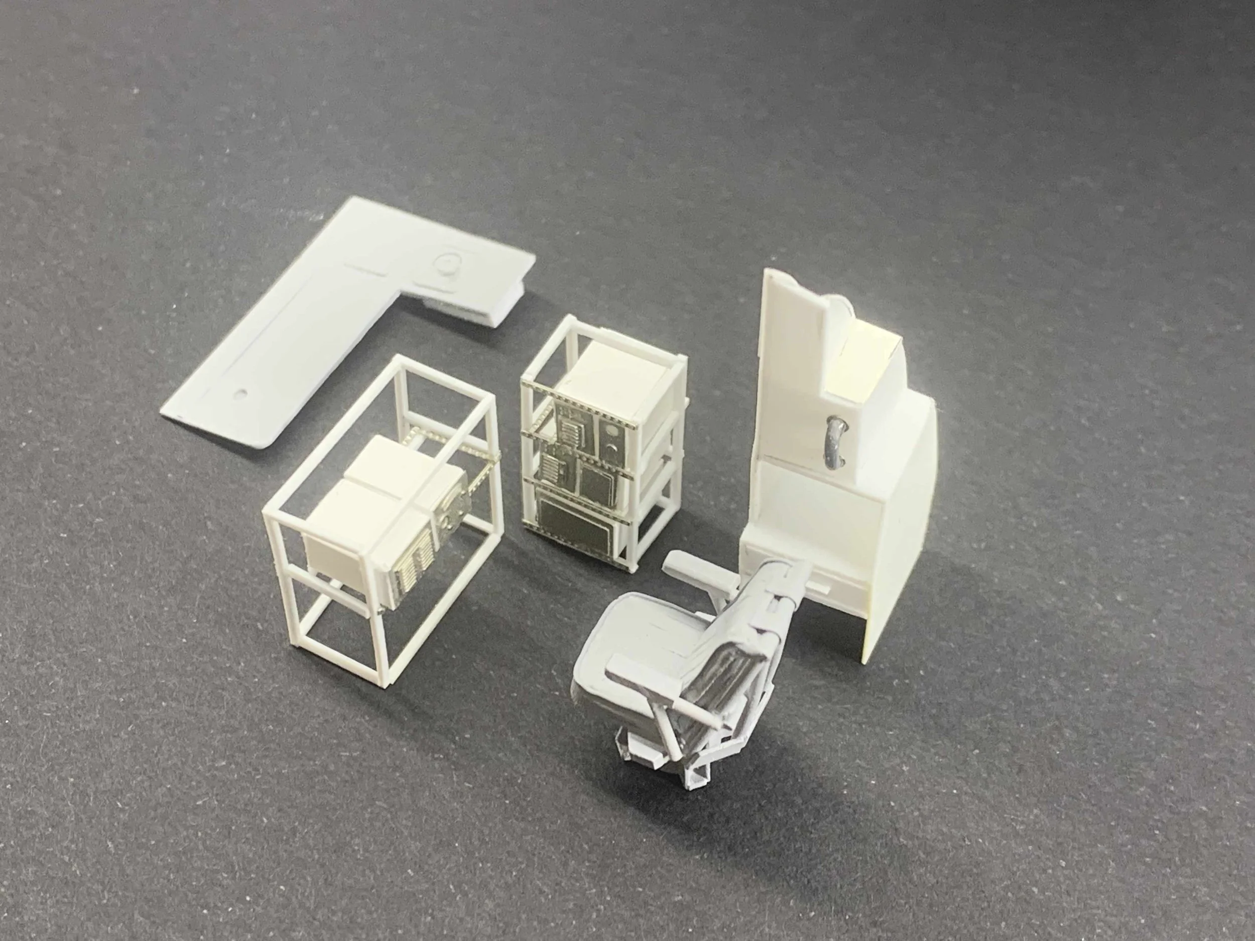
Bridging the gap: From 2D illustrations to the 3rd dimension. This process is deceptively tricky, requiring meticulous measurements and continuous fine-tuning. For these sections, the centre pedestal was 3D printed and the instrument panel photo-etched, but the pilot seats and consoles were crafted with traditional scratch-building techniques and materials.
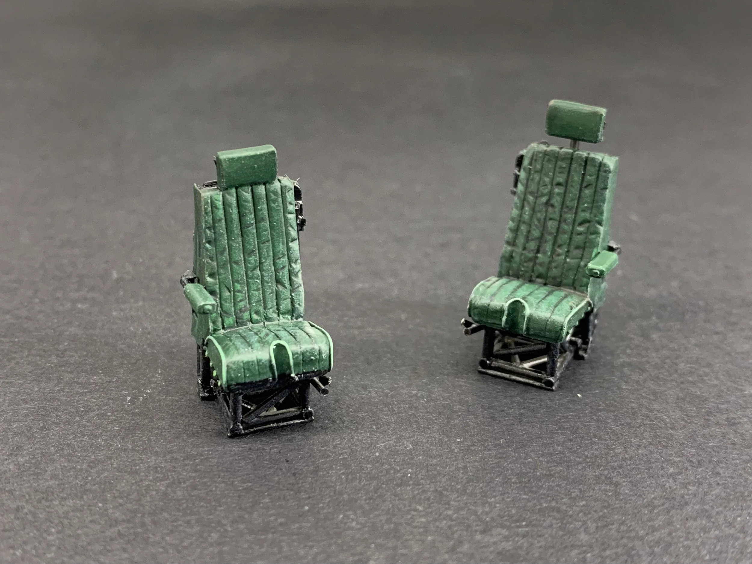
Crew Seats
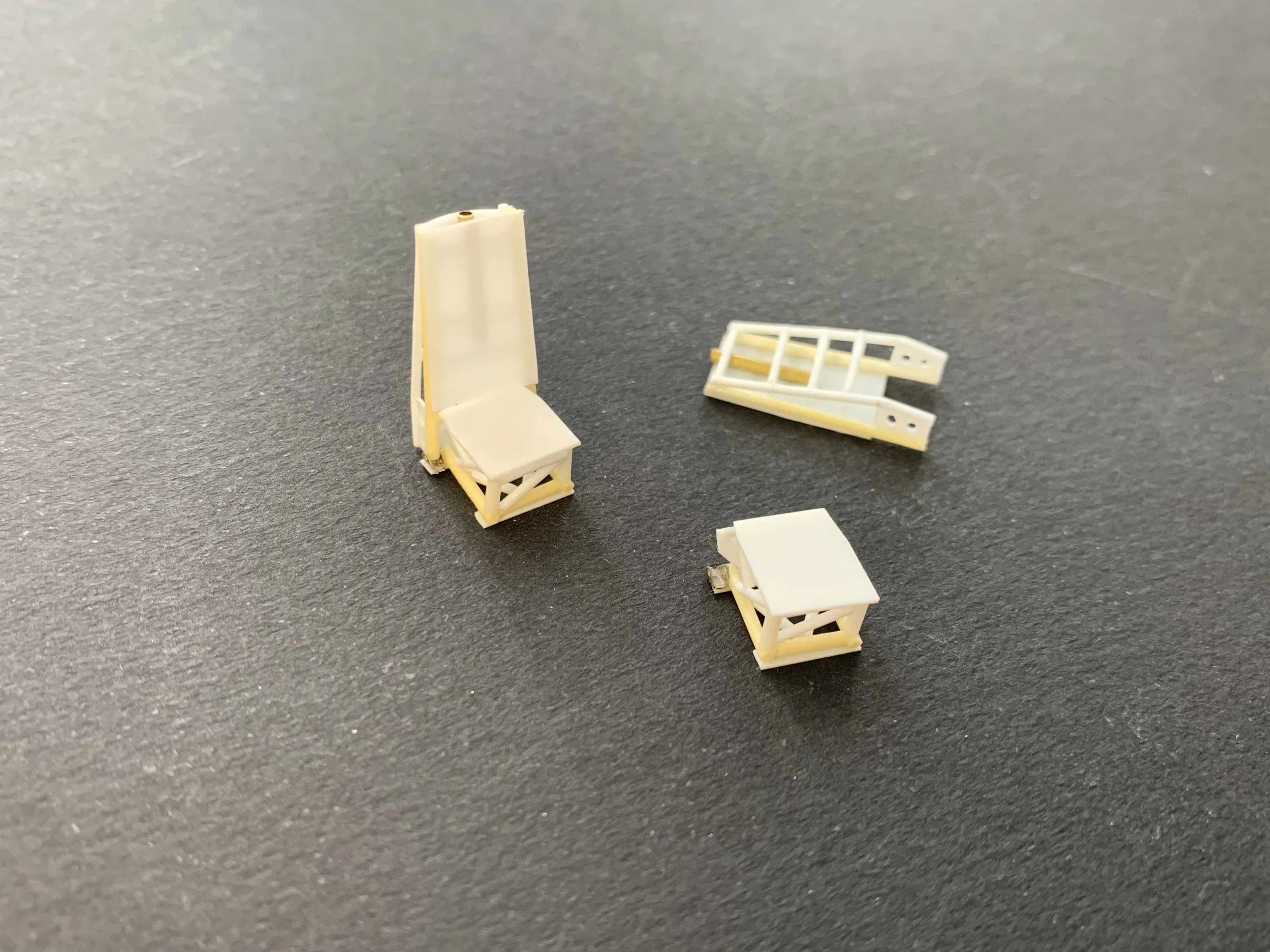
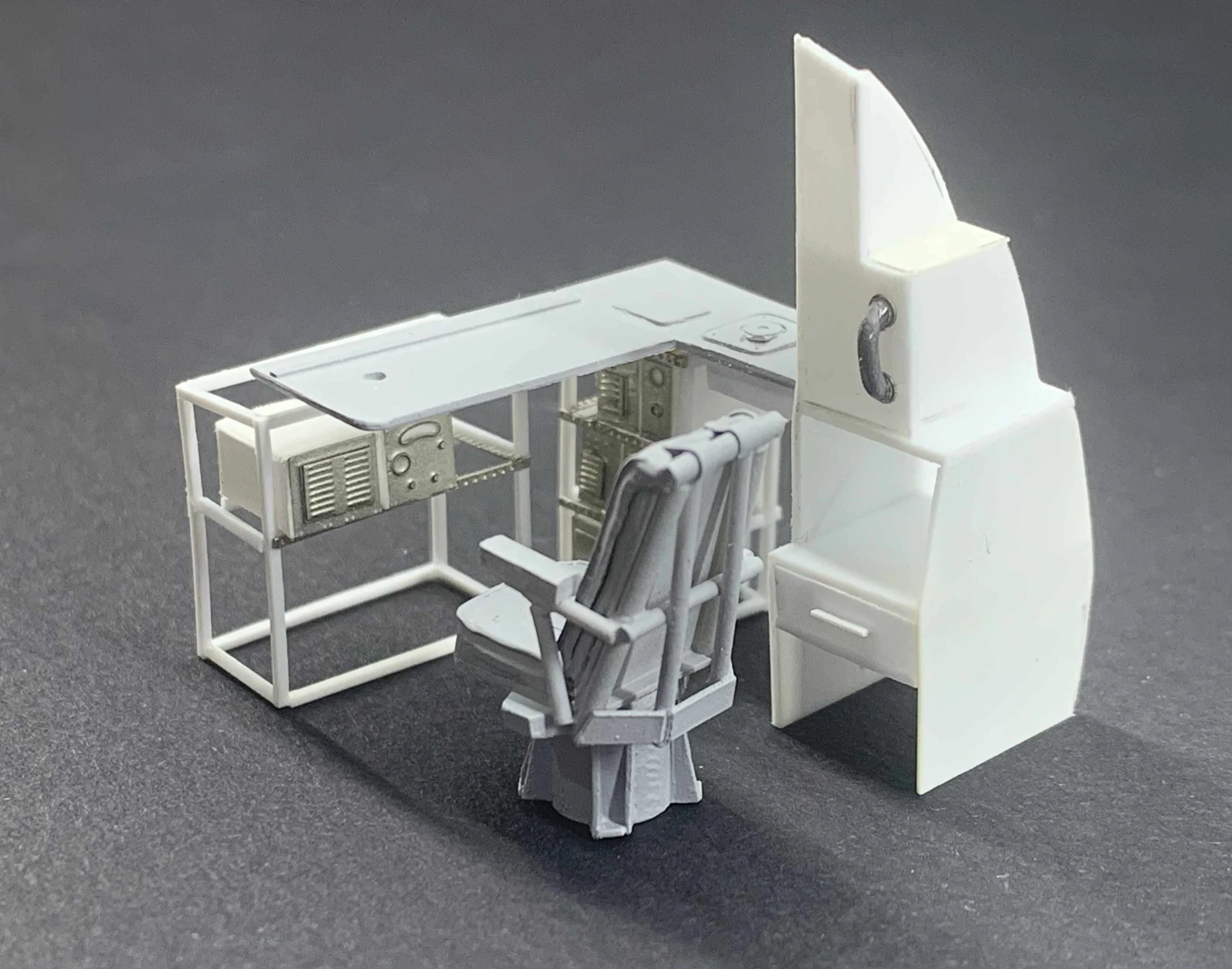
The pilot seats for both the Captain and First Officer were identical, and I crafted them primarily from plastic sheet and rods. For the cushions, I turned to Magic Sculpt for its versatility, and used 0.2mm lead wire to create the subtle cushion details. To further enhance their realism, I incorporated additional details using leftover photo-etched fittings. The Navigator & Wireless Operator seats were built in a similar manner.
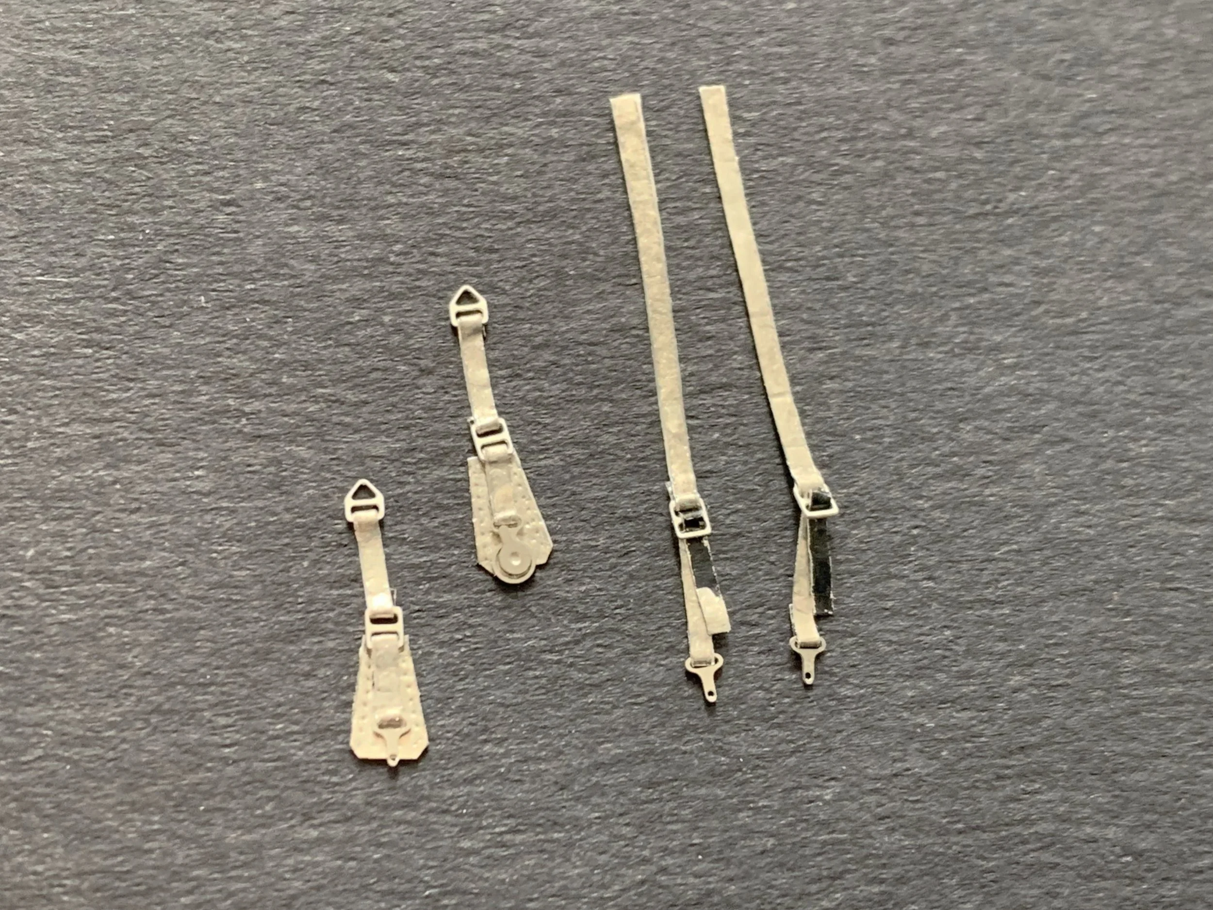
Once painted, I'll install the final touch: seatbelts with unpainted nickel silver buckles, which will provide a nice metallic contrast.


Layout Arrangements & Detailing
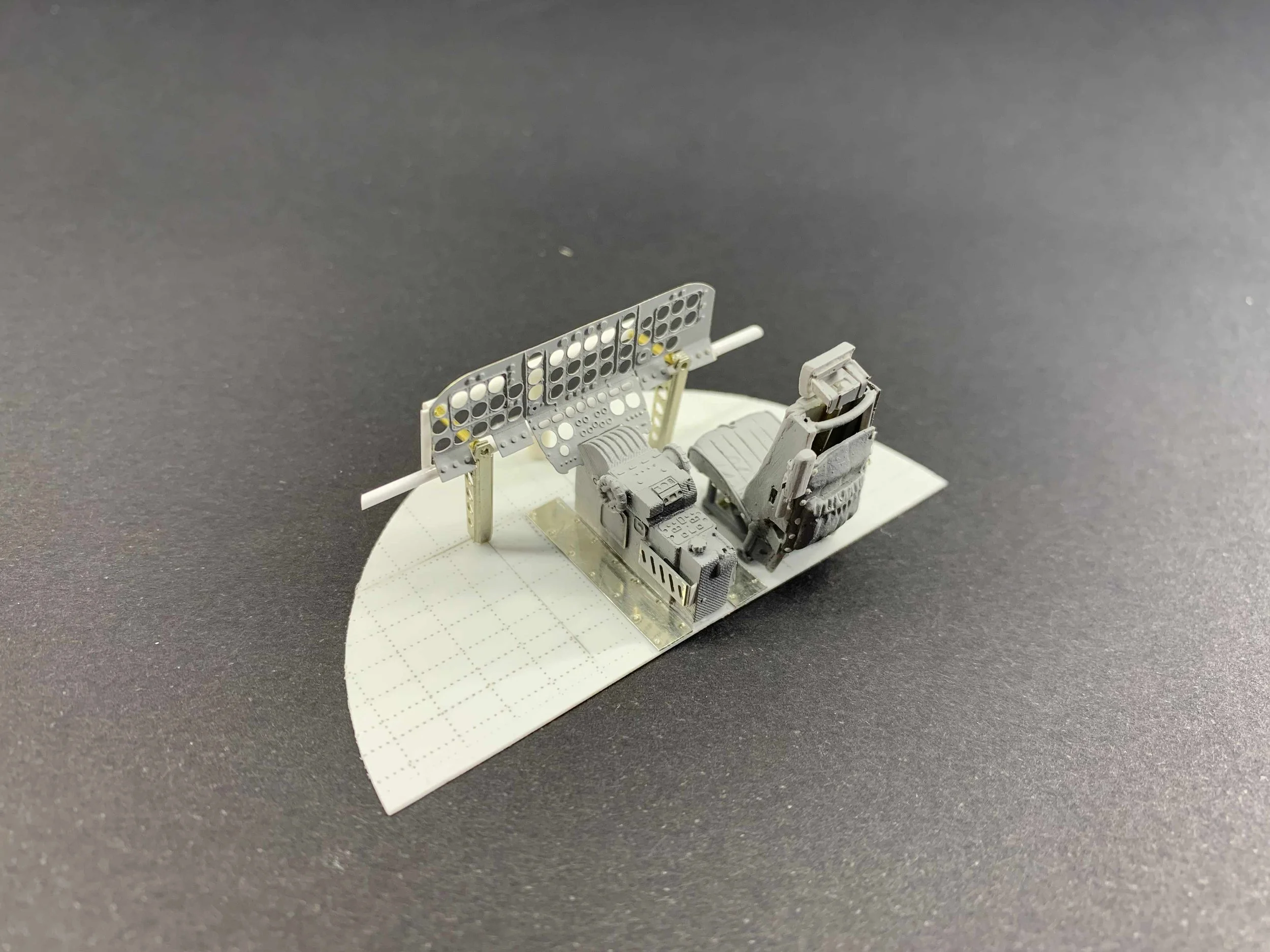
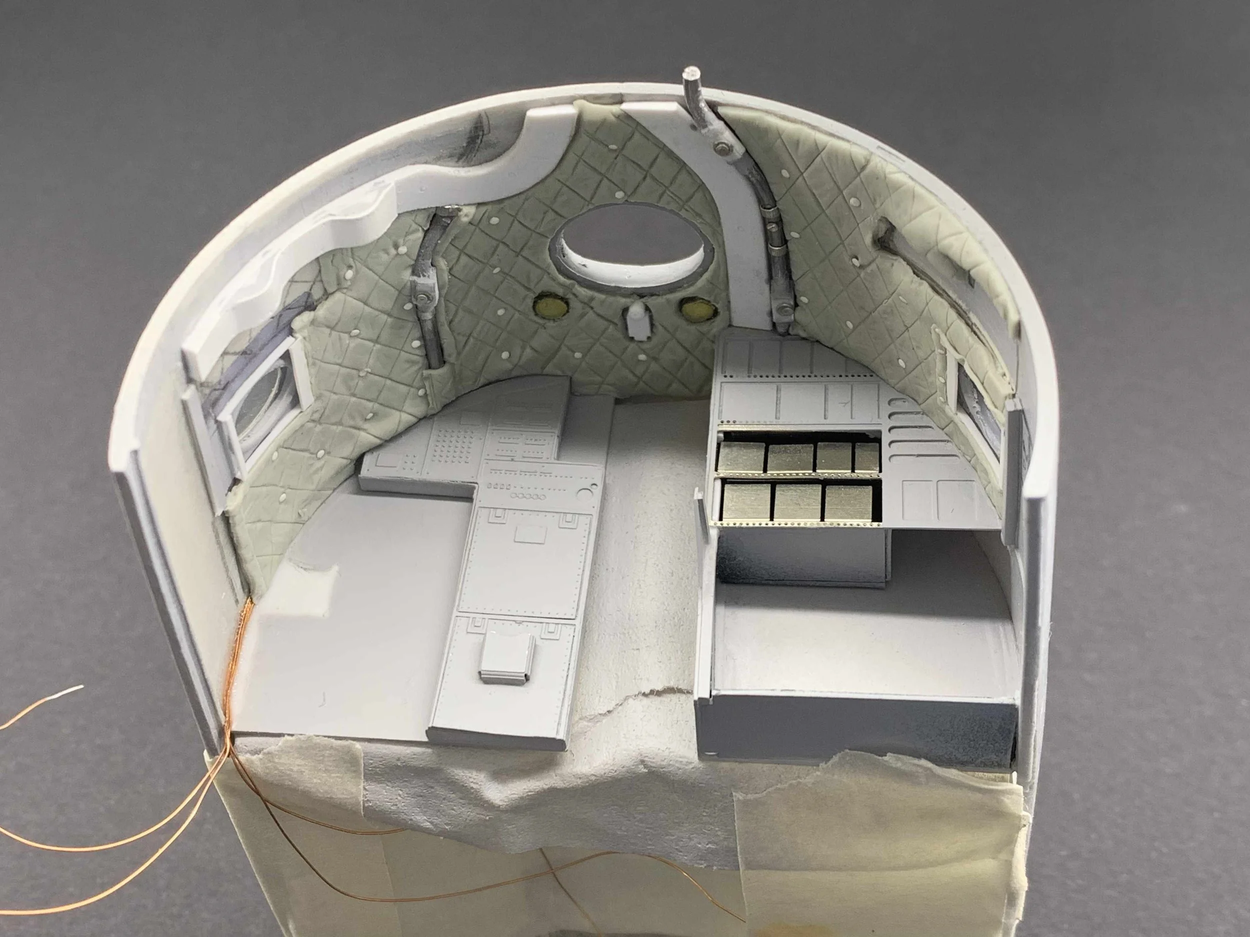
With the bulky flight crew seats having taken shape, I shifted my attention to the rest of the flight deck layout. A new 0.3mm floor was made and detailed with rows of rivets according to the Structural Repair Manual. A pair of metal panels on either side of the centre pedestal were crafted from pewter sheet and will be left unpainted for higher realism. The instrument panel and control column supports were of hybrid construction, including custom photo-etched parts, Albion Brass tubes, and plastic rods & strips. Similarly, the centre pedestal also featured a hybrid approach with 3D-printed and photo-etched components. The rudder pedals were based on photo-etched parts of my own design but proved to be much more challenging than originally anticipated. They have now successfully been installed in their appropriate location on the dashboard mounting tube.


Navigator & Radio Officer Crew Stations
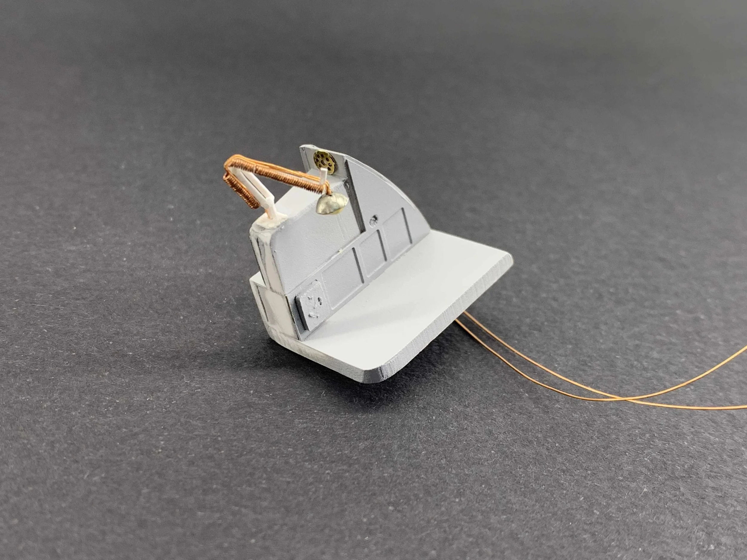
The Navigator and Radio Officer stations proved to be another opportunity for a resourceful mix of materials and techniques.
The circuit board panel behind the Navigator and other panels were created using photo-etching. For the Radio Officer's position, the table, equipment racks, and cabinet were primarily constructed from plastic. A particularly impressive feature is the pair of desk lamps for both positions, which I equipped with LED lights and enhanced with tiny wire springs. These springs were made by wrapping a piece of very thin piece of copper wire around a needle. You may note that they are slightly bulky for the scale, their cool appearance however made them worth keeping.
The ceiling also received significant attention. Air vents were represented by 1mm solder wire, and the wire loom channels were crafted from plastic. I also installed two dome lights, with their respective cables neatly concealed under the insulation blankets. To create these blankets, I sketched the equipment locations on a small piece of tracing paper, then transferred their shapes to a piece of flattened Magic Sculpt. A little talcum powder ensured the Magic Sculpt would cleanly lift from my worktop. The side of a scribing template was used to press in the characteristic square pattern at equal distances, and then an assortment of sculpting tools to add more visual interest to the blankets by creating various creases. Finally, studs were added to represent where the blankets were fixed to the aircraft structure.
The final step before applying a coat of Mr. Surfacer 1200 was a test of all the lights, making sure they were illuminating as intended.


Bringing the Flight Deck to Life
There's nothing more fulfilling than seeing months of labor become something substantial, and this couldn't be more true for the Britannia's flight deck. The ultimate goal was to make this intricate space come alive, to capture not just the vintage look of the aircraft but also the feeling of a well-used, operational cockpit. The challenge was to move beyond simply building a model and instead to create a miniature piece of history—a space that feels authentic and lived-in. Every detail, from the instruments to the wear on the seats, was crafted to evoke this sense of realism.

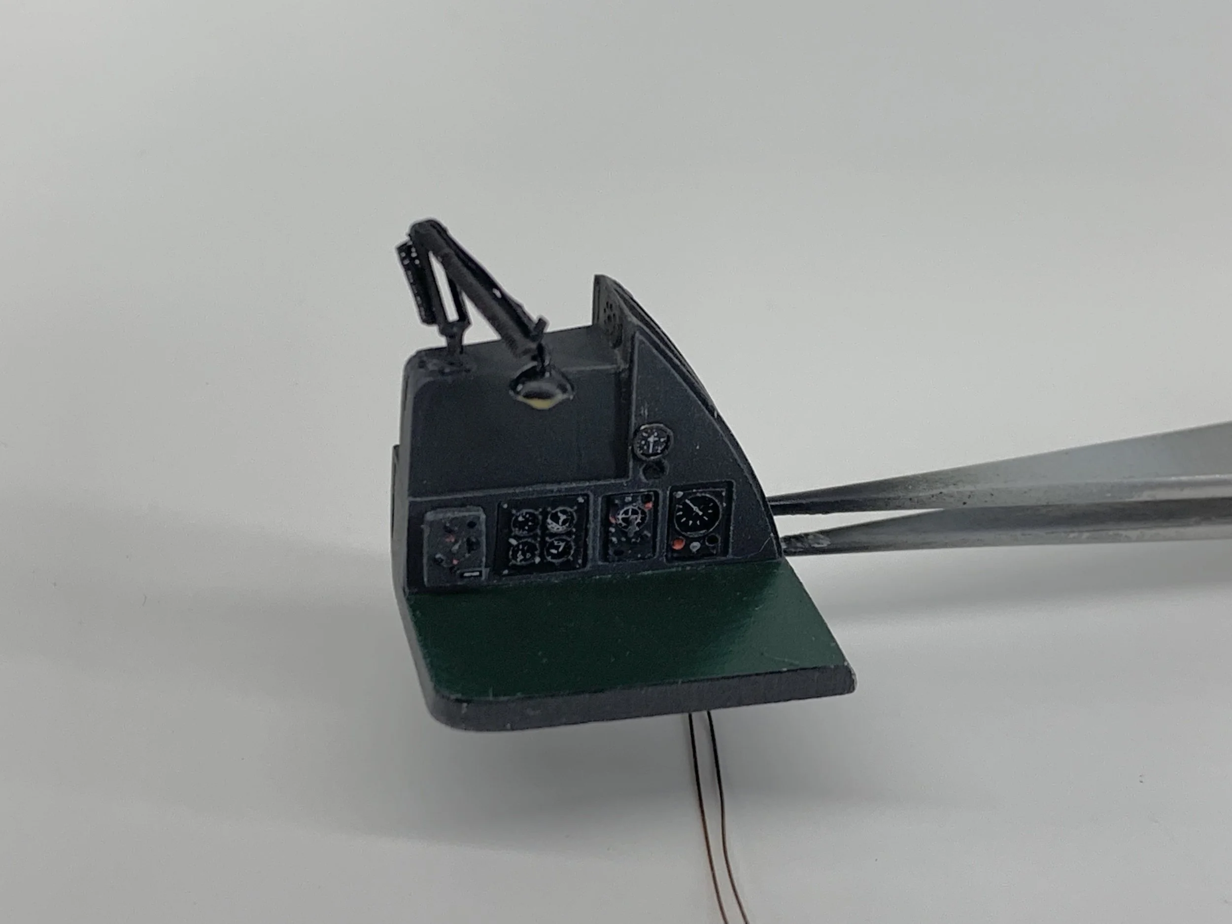
To create this vintage but also realistic effect, I used a variety of paints and materials. The instrument panel was painted with NATO Black, while the floor was a custom mix of Tamiya Gloss Black with a few drops of Tyre Black. Using a mix of matte, semi-gloss, and gloss blacks on the other components helped to differentiate them, adding depth and making the whole area more interesting and realistic.
To populate the instruments, I used excellent Airscale Instrument decals, which were kindly supplied by the company. The center pedestal, a 3D-printed resin piece, was detailed with custom-made levers fashioned from 0.5mm solder wire and tiny bits of plastic. I also trialed AK's markers to paint buttons and lights, which I found to be particularly effective. For a higher level of realism, the metal panels on either side of the center pedestal and the seat tracks were made from thin pewter sheet and left unpainted.


The crew seats were also treated to a variety of colours to highlight all the detailing work. The harness for each seat was a particularly time-consuming task, taking about an hour to make. Each was crafted from soft metal from a Dalwhinnie whisky cork cover and custom nickel-silver photo-etched buckles. They were then painted with three to four different shades of blue using Vallejo and Citadel acrylics. No alcohol was consumed during the process, but some was definitely required afterwards to celebrate the completion!


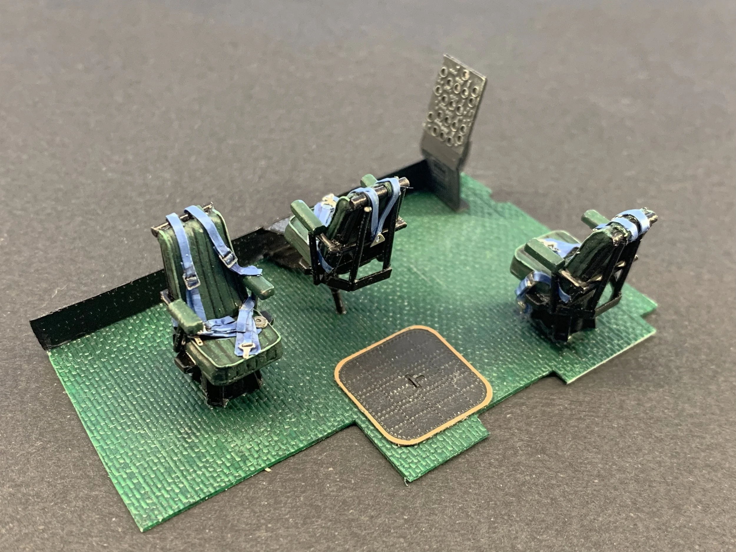

Ceilings & Equipment
The Navigator & Radio Officer stations were also painted with acrylics. The insulation blankets received a mixture of deck tan with a couple of drops of interior green, whereas the black components received a combination of matt and glossy black. A great addition was also an assortment of Airscale placards at various locations.


Ready for Takeoff
With the flight deck almost complete, the model's heart and soul are now in place. The painstaking work on the dials, levers, and seats has created a space that feels ready for a crew and a new journey. This detailed cockpit sets the stage for the rest of the build, ensuring that the Britannia will be a faithful and impressive tribute to its legacy.

My special thanks to Airscale for supplying their excellent products, which were “instrumental” in helping me bring the Britannia flight deck to life.