The Tale of a Very Large Tail
Designing & Building Britannia’s Empennage
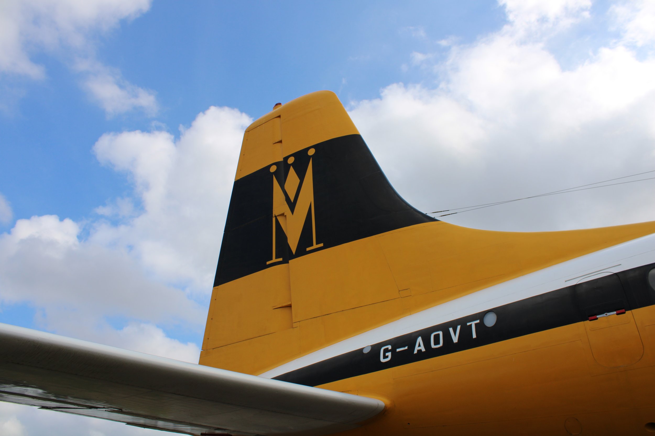
Tail Section of Bristol Britannia G-AOVT at Imperial War museum Duxford.
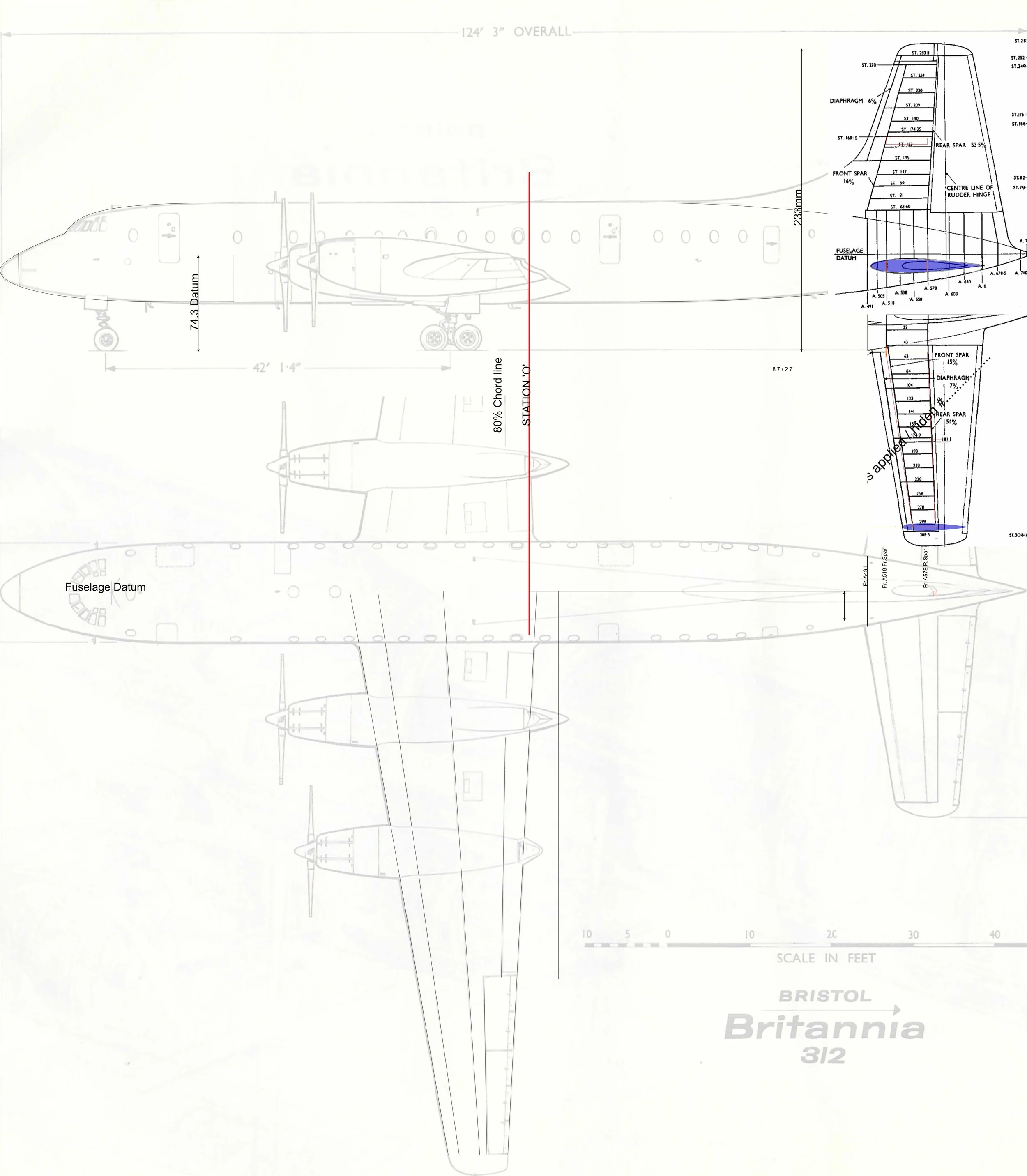
Designing the model's tail section, or empennage, was yet another significant undertaking. I approached it using my preferred numerical methods, while also relying on illustrations from the Britannia's maintenance and structural repair manuals. All this data was then transferred into Autodesk Fusion, with the exception of the curved fairings, which are still beyond my current design capabilities.
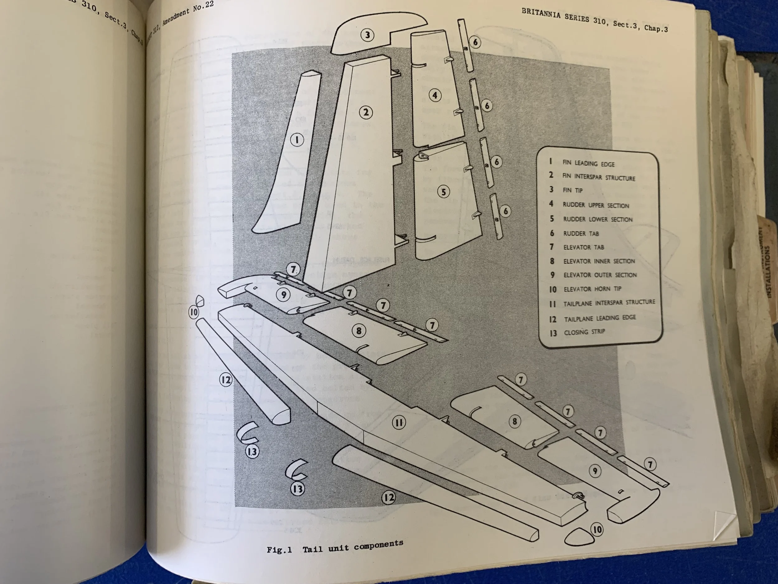


For the tailplane spars, I incorporated Albion Alloys 6 x 3mm brass I-beams to ensure strength and symmetry. A pair of brass rods served as guide pins for the vertical fin, while the elevator and rudder hinge fittings were crafted from 1mm thick brass strip to achieve the highest possible strength.
The fairings required a combination of pewter sheet and Milliput epoxy while the fin tip and elevator horn tips were crafted from PU model board and styrene plastic. As is almost always the case with any scratch-built project – and despite the clear advantages of 3D printing – getting these parts into shape involved a tremendous amount of sanding.


