Designing & Building Britannia’s Iconic Nose
Britannia’s nose section spanned between frame stations F.493 and F.619. This part of the aircraft was made up of two major components: the spherical “primary structure,” which bore the significant loads of flight, ground operations, and pressurisation, and the conical nose, a “secondary structure” designed to handle only aerodynamic and inertial forces. The key difference between them was that a failure in the primary structure could compromise the aircraft's overall structural integrity, whereas a failure in the secondary structure would affect operation but not lead to the loss of the aircraft.
From a modelling perspective, I faced the challenge of seamlessly combining these two structural types using 3D-printed ABS and vacuum-formed styrene. This combination needed to provide the necessary rigidity for the resin nose landing gear – which would be reinforced with metal rods – to support the weight of the finished model. Furthermore, I had to incorporate provisions for two separate lighting circuits (one for the 9V LED strips and one for the 3V individual lights) to run through the nose gear leg and nose wheels to the base, and subsequently to the batteries and switches. Finally, the model’s vacuum-formed canopy would need to sit precisely in its designated location, offering the best possible transparency for the cockpit details while maintaining near-perfect symmetry and a flawless transition from the nose to the main fuselage. Daunting as this may seem, let me guide you through the process, one step at a time…
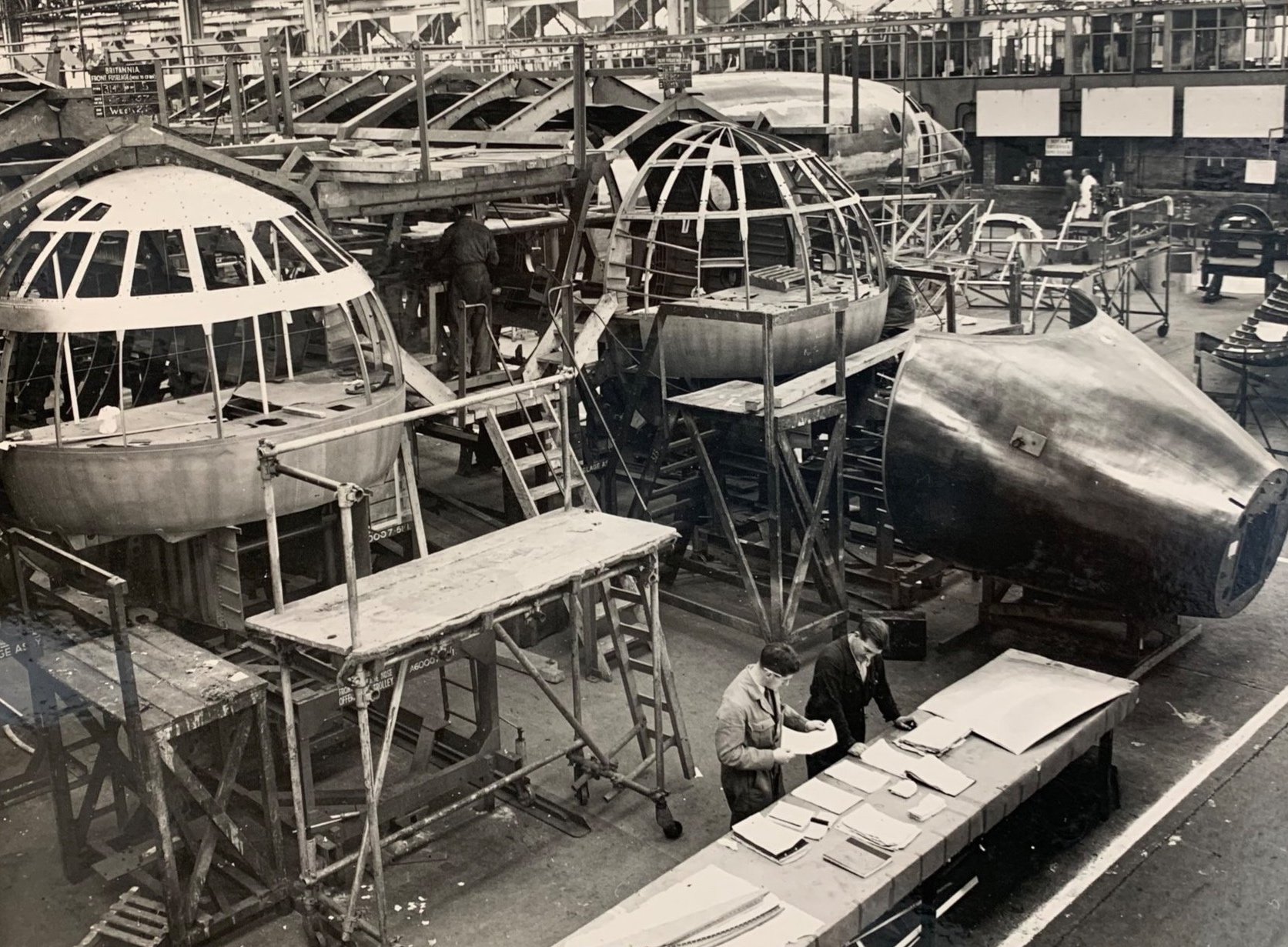
This photograph illustrates the main components of the Britannia's nose section. The canopy and windscreen framework, connected to the flight deck floor, together form the spherical pressure structure. Frame station F.493 is marked by the larger circular frame at the rear of the canopy and the back end of the flight deck floor. To the right, the nose section comprised of frame stations from F.619 (the radome attachment bulkhead) to F.548. (Source: Public Records Office Northern Ireland)
Design
Considering the aircraft setup and the model’s structural and practical requirements, I realised that the model nose needed to include the structure from the tip of the Radome to frame station F.493. This single plastic component would not only accommodate the numerous cockpit details but also provide a solid base for the intricate and challenging canopy.

This image displays the nose section study (top) and the design of the main plastic components for the vacuum mold base (bottom). Notice the inclusion of an extra frame at station F.553, designed as a reference point for the canopy. The design was also scaled down to accommodate the approximate 0.7mm plastic thickness post-vacuum forming.
Crafting the mould
The previously designed frames were cut from 2 mm styrene and assembled. My first attempt with 1mm plastic proved unsuccessful due to insufficient rigidity, leading to distortions. The gaps between the frames were then filled with PU model board, soaked in thin CA glue and sanded to shape. This was followed by a layer of P38 body filler, left to dry for around 30 minutes, and further sanding. Finally, the pieces were treated with Milliput Superfine epoxy, more sanding, and a couple of coats of Mr. Surfacer 1000.


Vacuum Forming
The moulds were secured to my custom vacuum forming machine with double-sided tape. I usually start with a thinner plastic test run to check oven temperature and overall functionality. The production noses were formed from 1mm styrene sheets, which typically thin out to about 0.7mm during vacuum forming. After creating two, the best one was chosen for the model. The nose landing gear box, made using photo-etching, will provide the required strength for the upcoming nose landing gear strut.


Nose Landing Gear
Before moving on with the flight deck details, the nose gear assembly had to be constructed and installed. It was crucial to design it with sufficient strength to support the model’s weight ( I expect it to be over 1kg ), while also allowing for four cables to run through, accommodating two separate lighting circuits. All design work was undertaken in Autodesk Fusion, with the aim of having the gear leg assembly 3D printed in resin. To further enhance its structural integrity, provision was made to install Albion Alloys aluminium and brass tubes in the wheel axle, oleo shock absorber, and trunnion.

Cross Section of Nose Landing gear design in Autodesk Fusion. To simplify the diagram the route of the electrical cables is shown only for one side.
Prototyping and Assembly
With the design complete, it was time to put it to the test.
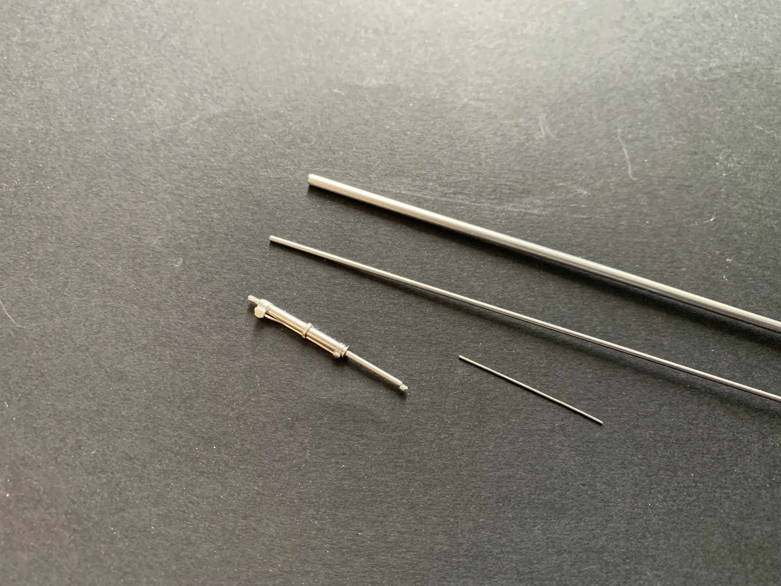
The gear strut oleo was represented by a 3mm Albion aluminium tube. The critical length of Dimension ‘A’—commonly referred to as the visible part of the oleo between the main leg and the wheel axle assembly in maintenance documentation—was calculated using the maintenance manual's servicing instructions.
Next, a 2mm aluminium axle was installed, followed by a pair of female miniature connectors, one in each wheel. The individual wires for the lighting circuits were then painstakingly guided through the leg, axle, and wheels before being soldered to each connector.
Despite having made provision for an extra 2mm telescopic tube to pass through the 3mm oleo, it proved impossible to route all the necessary cables. Ultimately, I had to omit this additional tube to get the wiring through as intended. Finally, the model’s 2 mm solid brass trunnion will be cut accordingly to allow the vacuum formed nose section to be installed.


Detailing the Nose Gear Bay and Leg Assembly
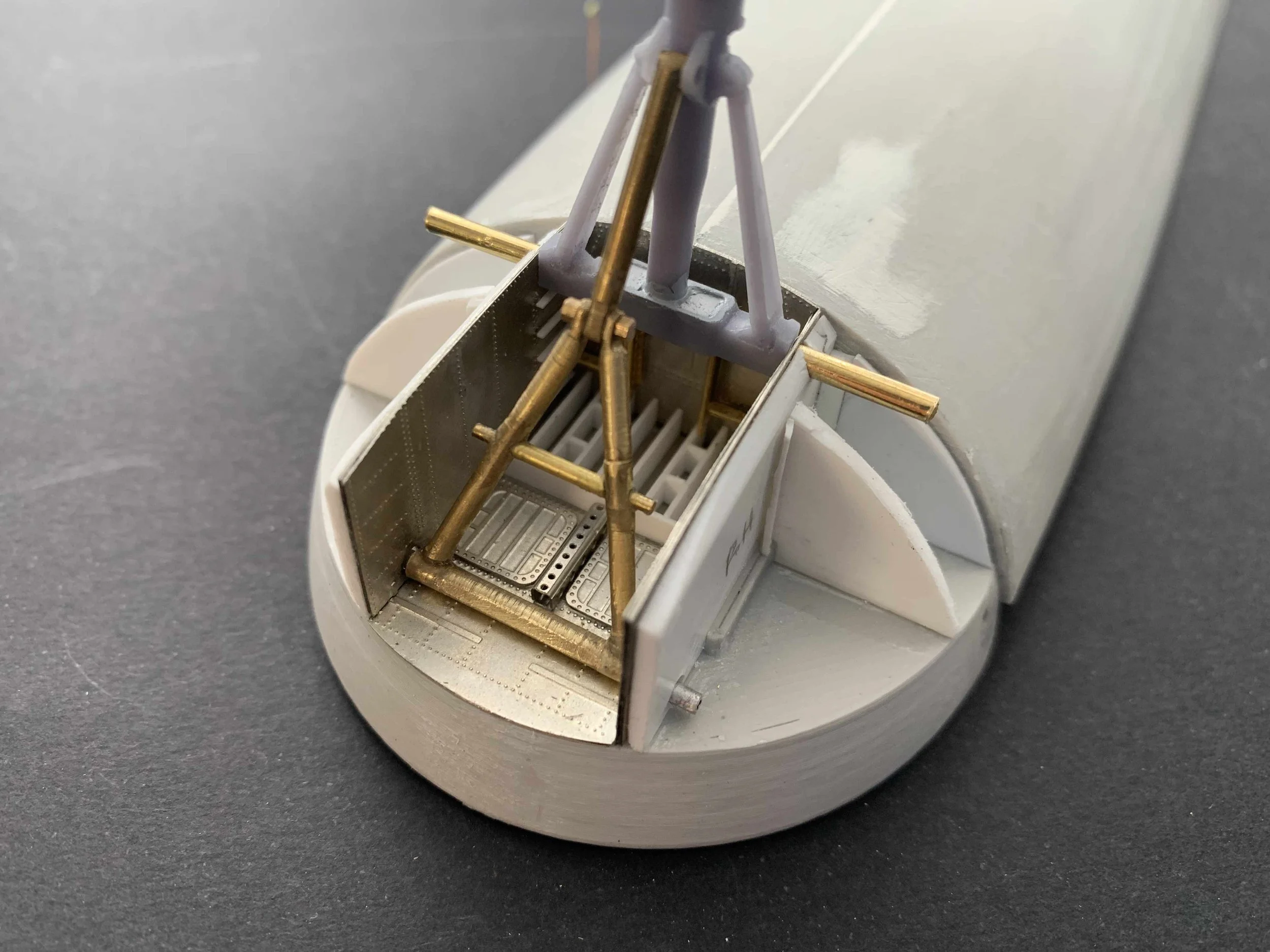
With the primary assembly now complete, attention turned to detailing the wheel bay. This area was brought to life using custom photo-etched parts, further enhanced with styrene strips and various leftover photo etched brass from my Empire flying boat model. The gear leg itself also received significant detailing with an array of fittings, as illustrated below. A prominent feature on the aft side is the actuator for the nose wheel steering system.
The retraction jack was crafted from two telescopic Albion aluminium tubes, 2mm and 1mm respectively. While this component serves no structural role in the model, I meticulously shaped it using my Proxxon mini modeling lathe to achieve the desired industrial look. This was further detailed with an aluminum-coated copper wire, representing the rigid pipe for the jack's retraction function.
To compensate for the earlier omission of the 2mm internal tube from the gear leg, I decided to craft the drag strut using brass rods. My lathe was yet again invaluable here, allowing me to shape the components with an industrial aesthetic. After several hours of focused work – and admittedly, some aching fingers – I finalised the basic form. For the joint between the upper 'Y' shaped and lower single radius rods, I used an out-of-scale but structurally necessary 0.5mm brass nut and bolt.
Further details were then added, including the bell cranks and connecting rods for the mechanically-retracted forward nose gear doors. All gear components received a couple of coats of Mr. Surfacer 1000 before being painted with Alclad Aluminium and a light blue primer.


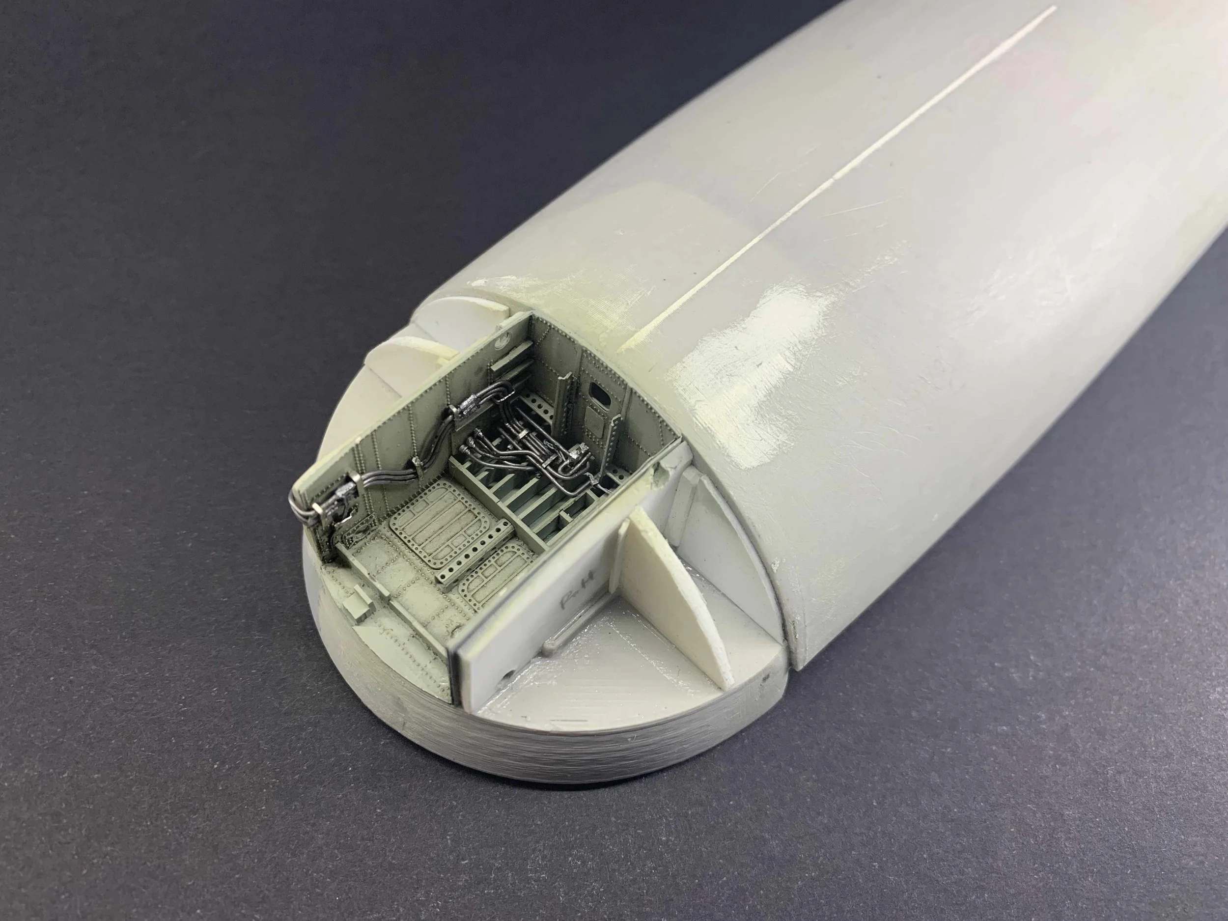
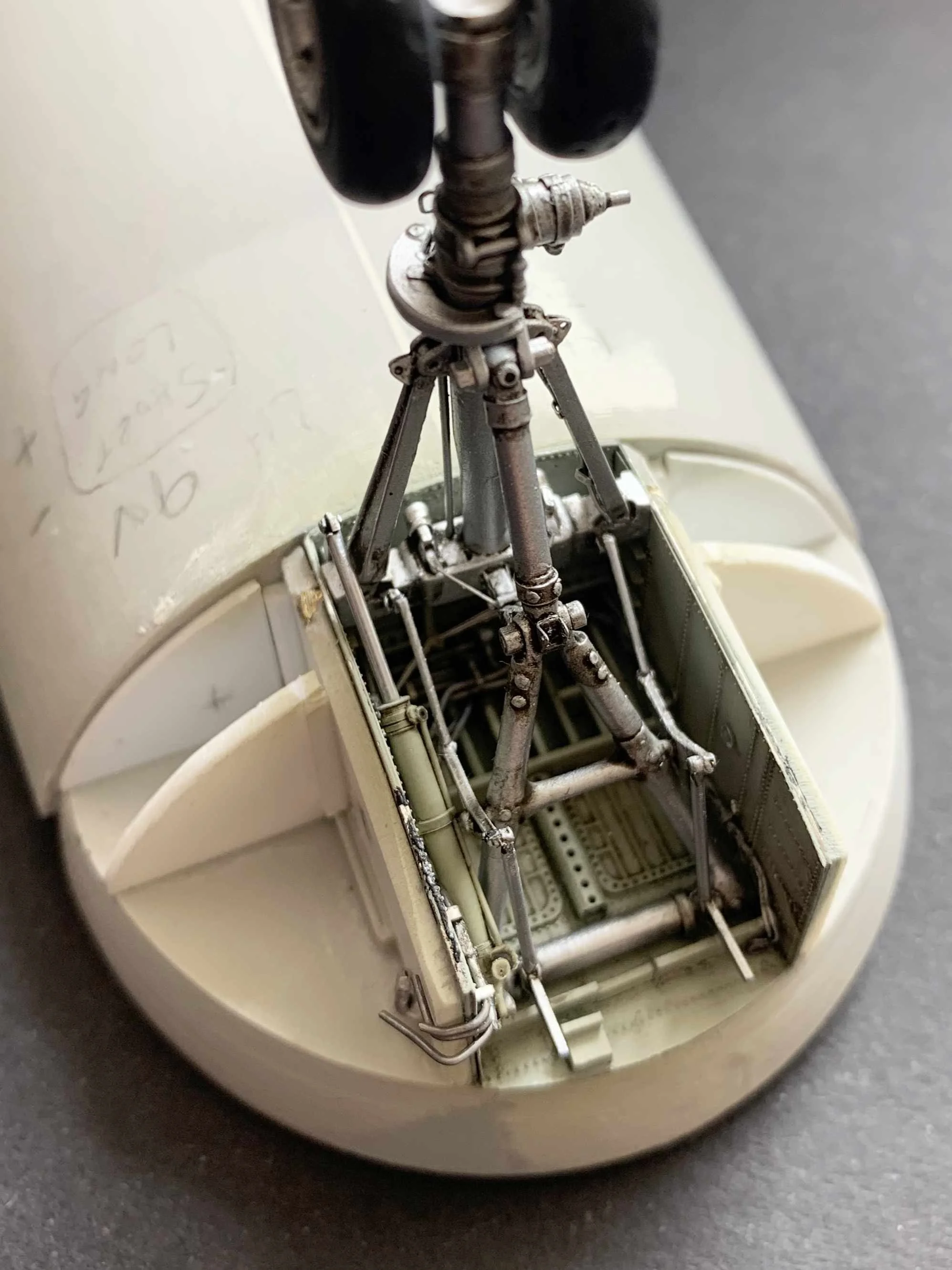
Nose Gear Final Details
The nose gear bay was finalised by updating the interior colour to a more plausible light green and an assortment of hydraulic pipes and rods. The ‘Y’ shaped strut assembly was secured to the main leg with a miniature 0.5mm nut and bolt. Finally, he retraction jack was installed in its intended location thus completing the nose gear assembly and this portion of the model.


Acknowledgments
At this point, I want to express my sincere gratitude to Albion Alloys for providing me with all requested materials. Their high-precision products were absolutely essential in bringing this design to life; without them, this undertaking would have been nearly impossible.
Finally, I feel obliged to praise the advent of 3D printing technology. It's truly a game-changer, offering immense creative potential while simultaneously providing significant time savings. Without it, achieving this level of detail and precision would have been far more challenging, if not impossible.