The Flaps Conundrum
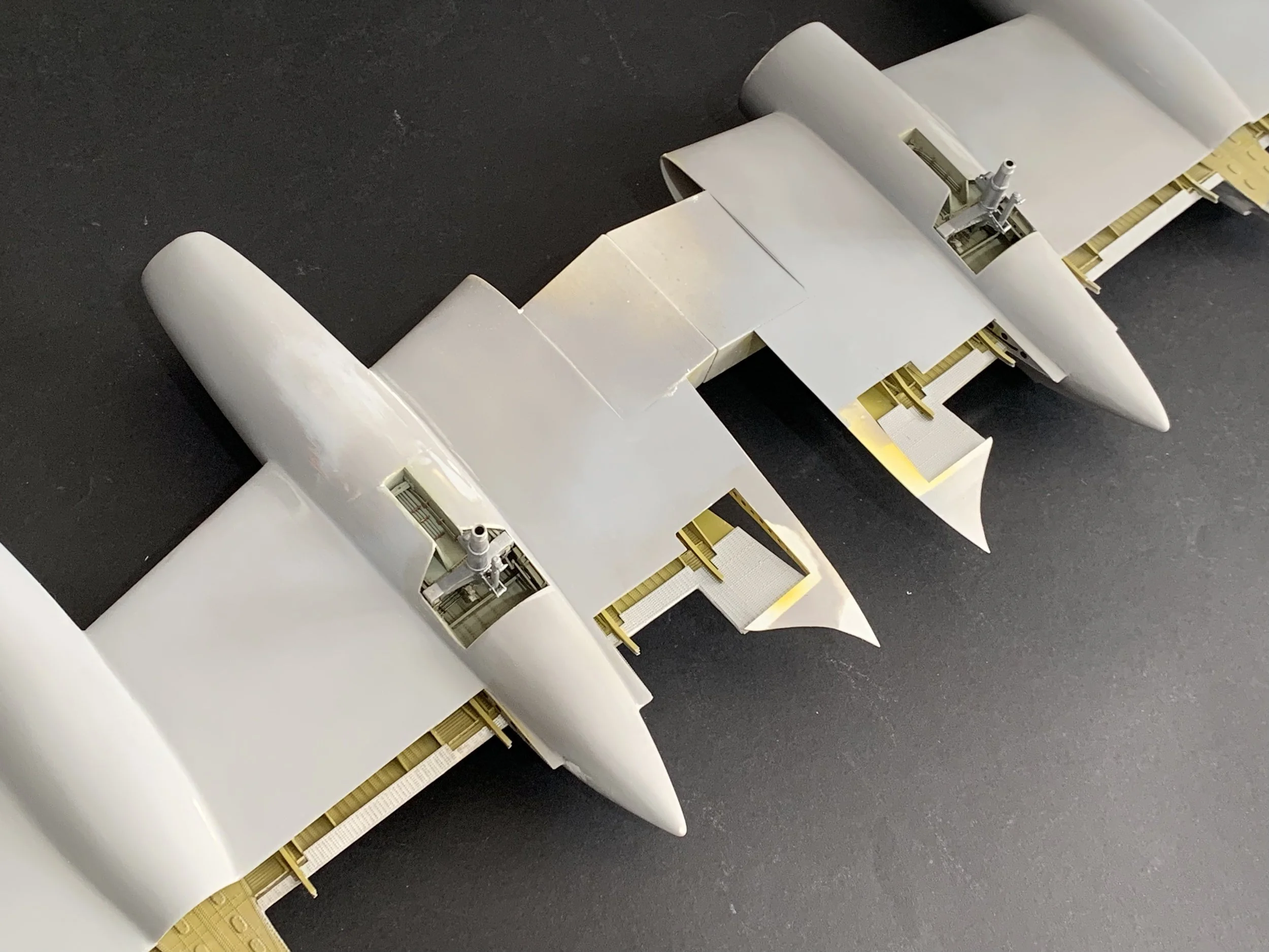
Lowering the flaps on any model adds an instant layer of drama and mechanical complexity, but for an aircraft with the presence of the Bristol Britannia, it felt less like an option and more like a necessity. Given the sheer scale of the build, I was determined to present the flaps in a deployed position, regardless of the extra engineering and effort required. My breakthrough came when I discovered that G-ANCF preserved at Liverpool Airport has its flaps removed, thus offering a rare view of the internal structures that are usually hidden from sight. I turned this discovery into a field trip to Liverpool, capturing dozens of reference photos and taking detailed measurements. Combining that hands-on data with original Maintenance and Repair Manuals as well as the Illustrated Parts Catalogue (IPC), I began the process of translating mid-century aviation engineering into scale-model reality.
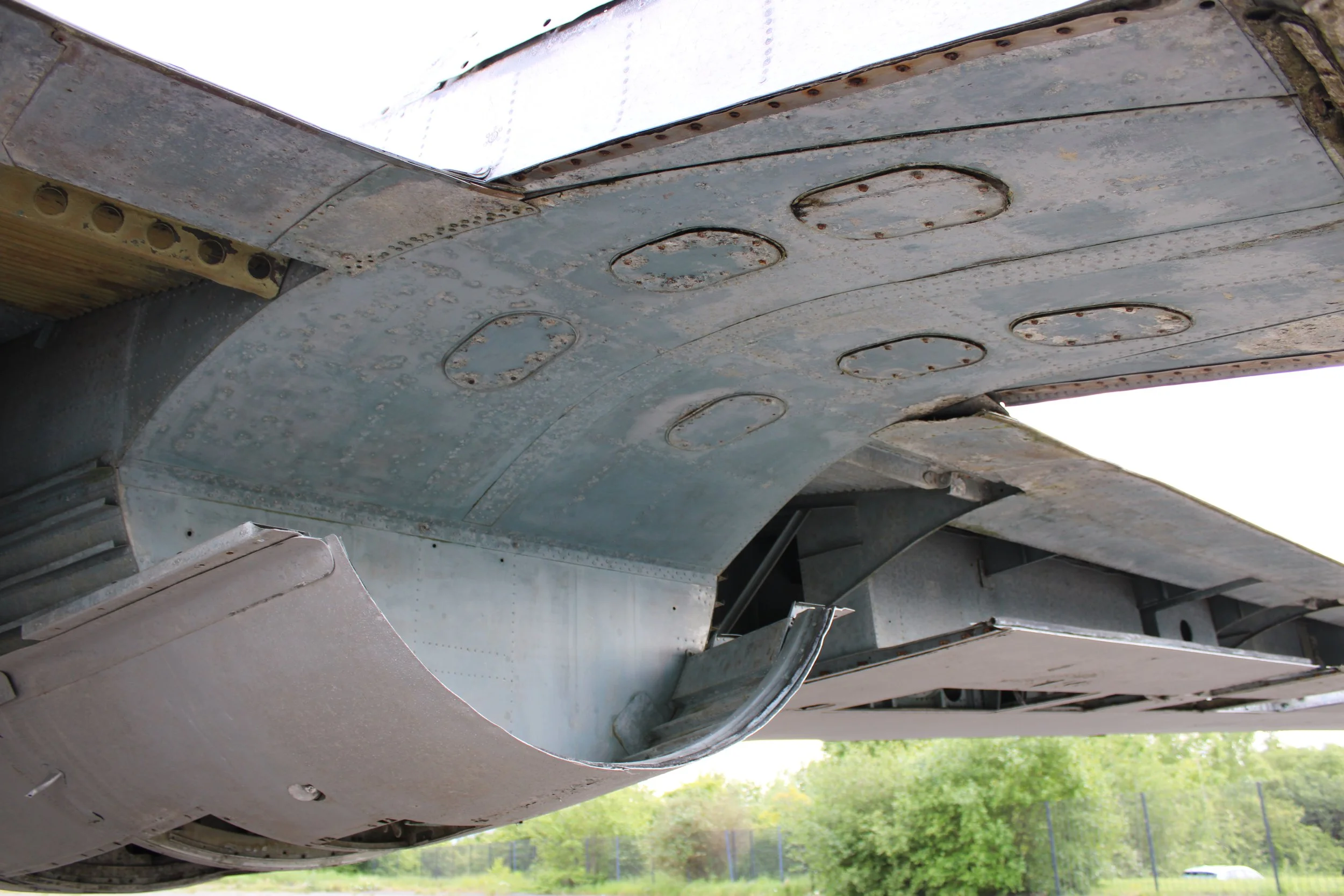
A representative image from G-ANCF flaps housing interior structure.
From Stations to Structure: Engineering the Internal Framework
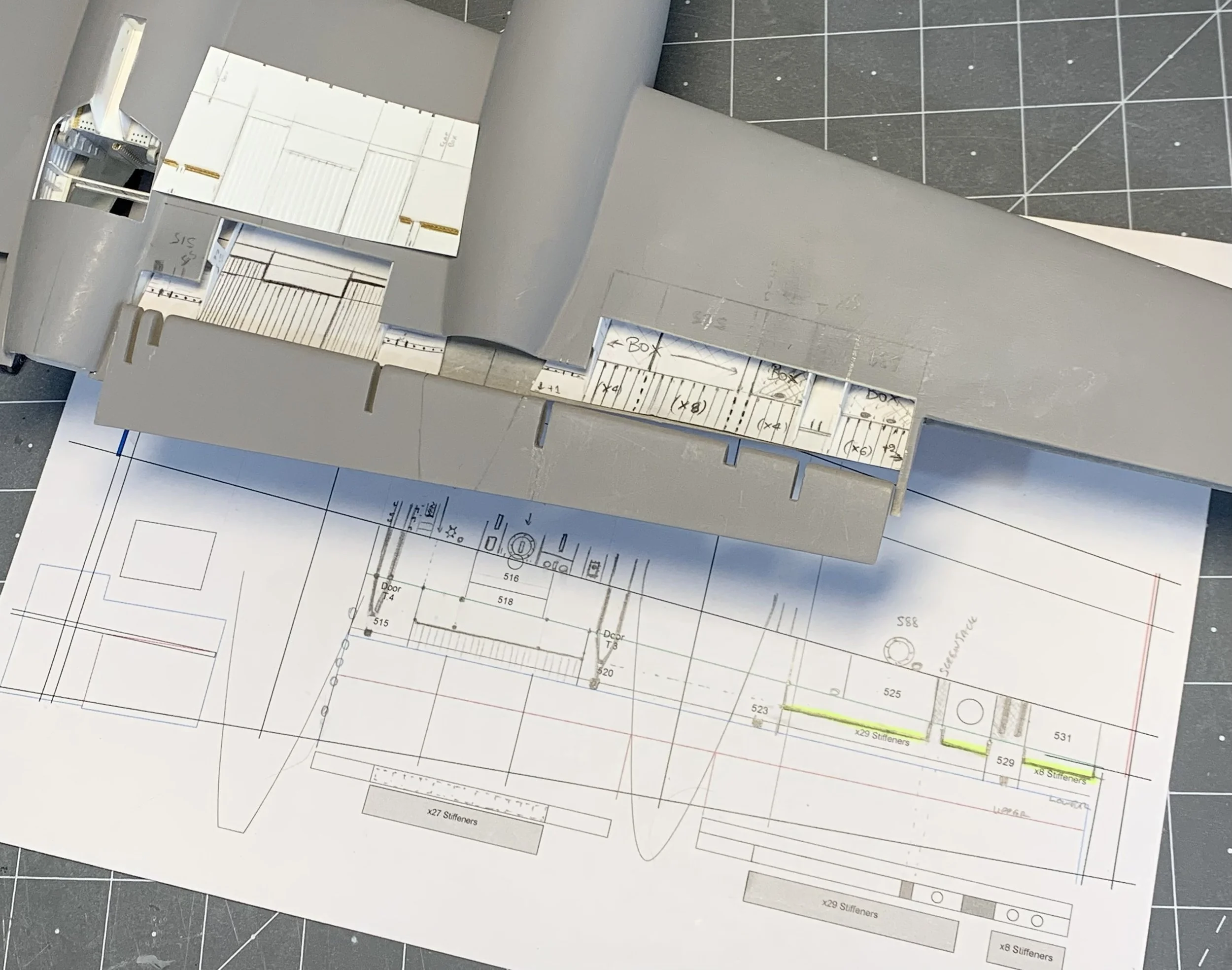
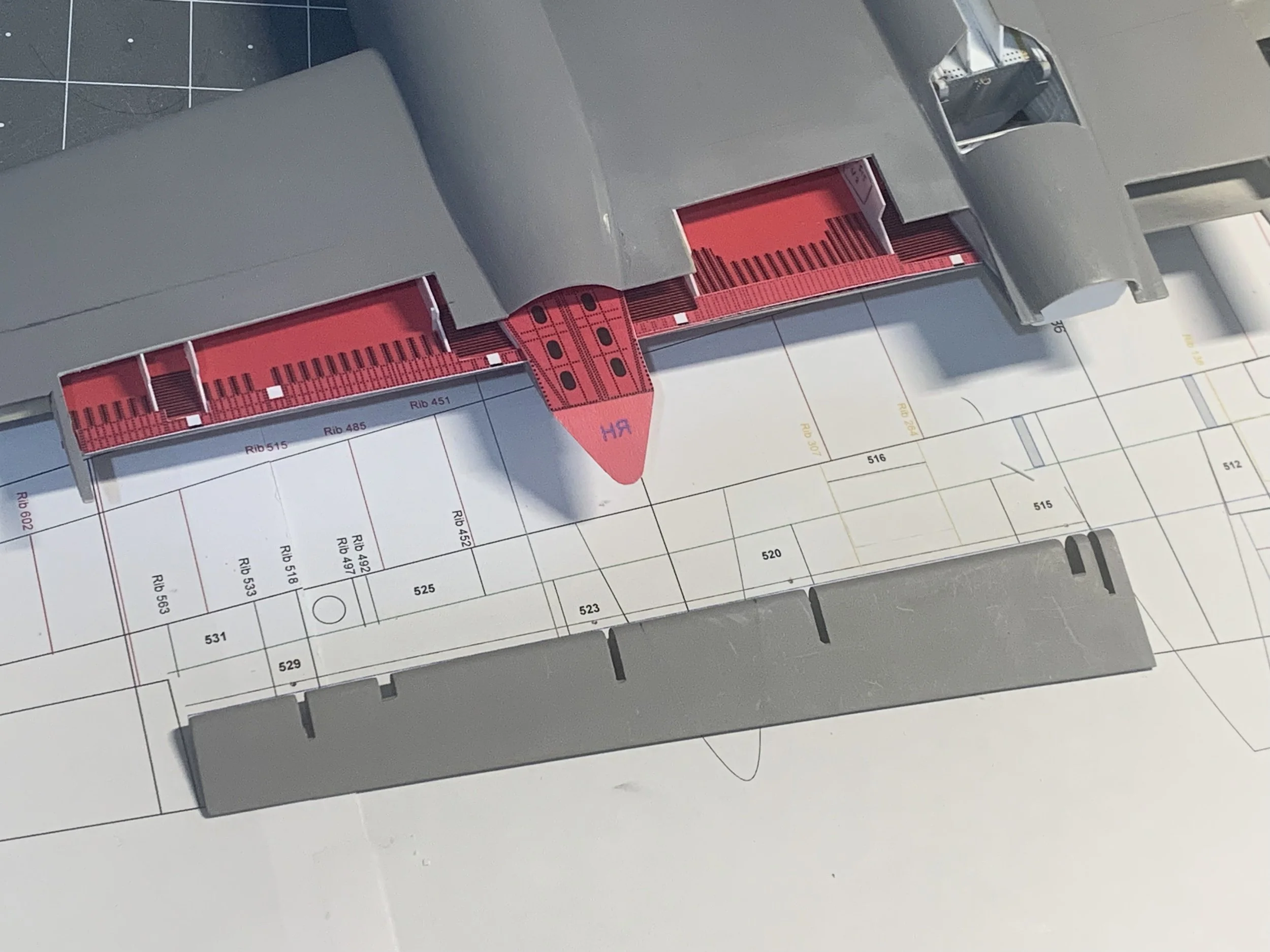
My process began with the basics: paper, pencil, and 2D drafting. Using the measurements I took at Liverpool alongside the official station numbers, I began mapping out the internal geography of the wing. For those unfamiliar with aviation drafting, station numbers are expressed in inches from a fixed datum line; in this case the longitudinal axis of the aircraft.
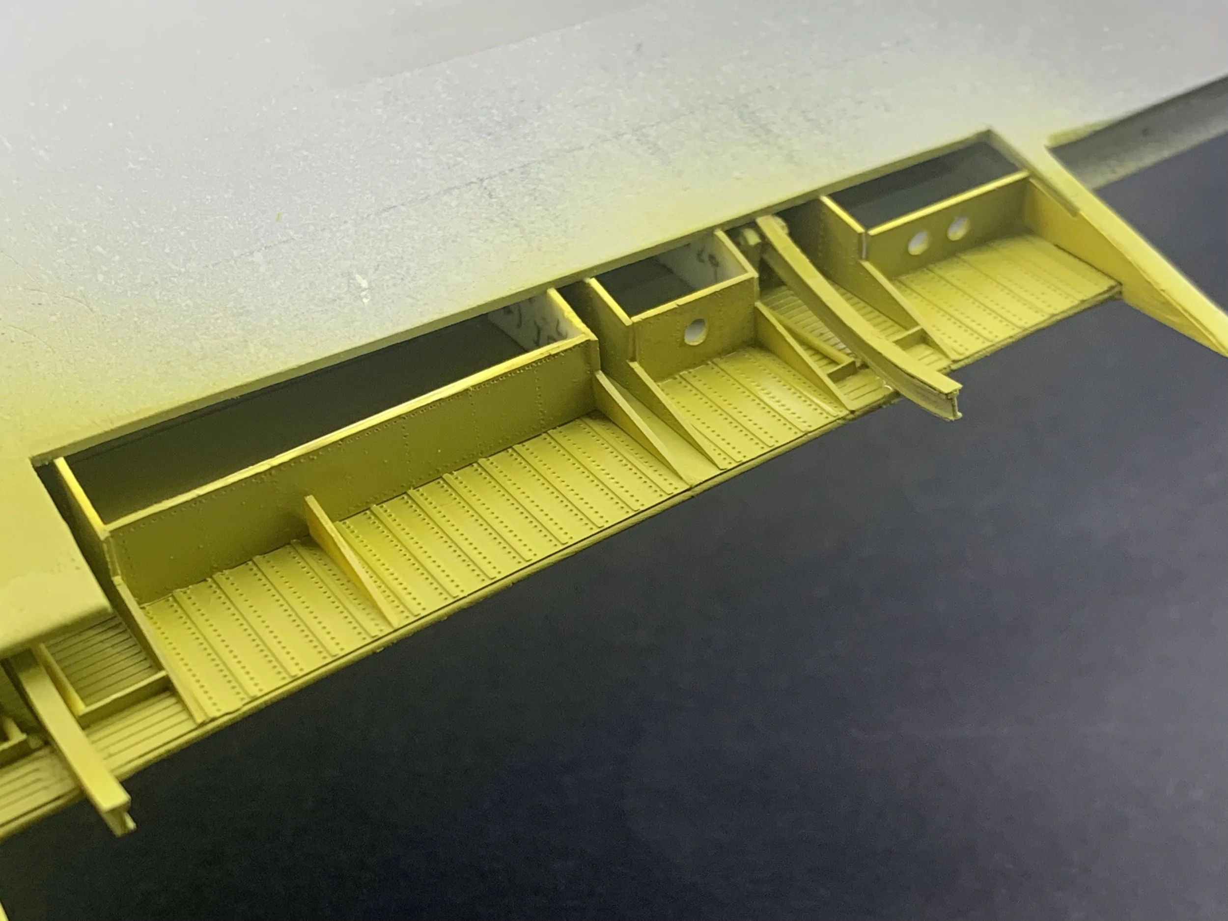
I’ll take a moment here to address a common hobbyist myth. No serious modeler actually "counts rivets" for the sake of it. However, counting ribs and stringers is an absolute necessity. If the structural spacing is off, the entire visual "weight" of the aircraft fails. You aren't just placing bits of plastic on the model for the sake of looking nice; you are replicating the structure that holds the Whispering Giant together.
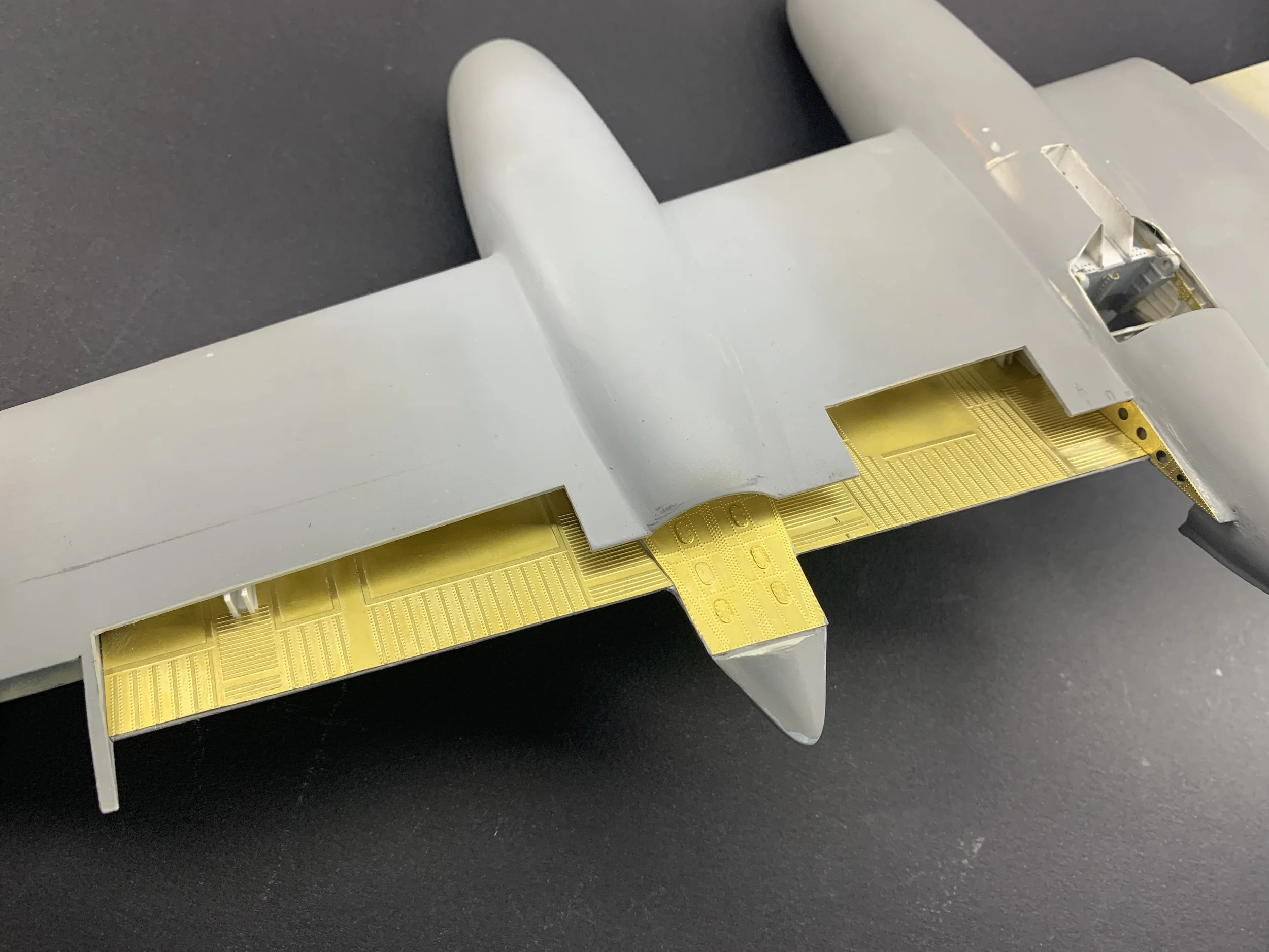
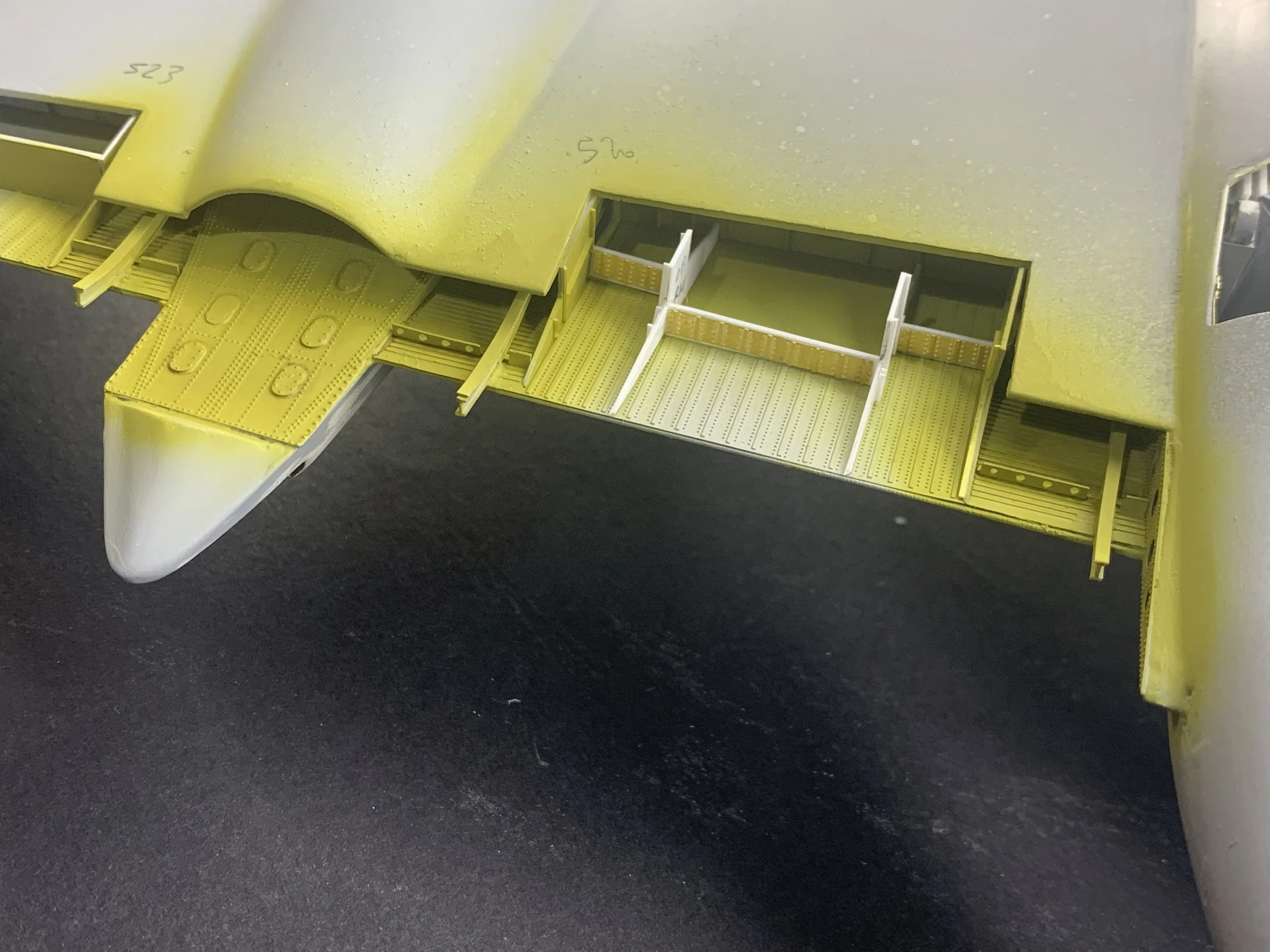
After cutting two sections from each wing to allow more space for the installation internal structure and details, I faced a classic modeling dilemma: how to represent the dense rivet lines on the wing ribs.
I experimented with Archer transfers and traditional riveting wheels, but the precision I wanted led me to a hybrid approach:
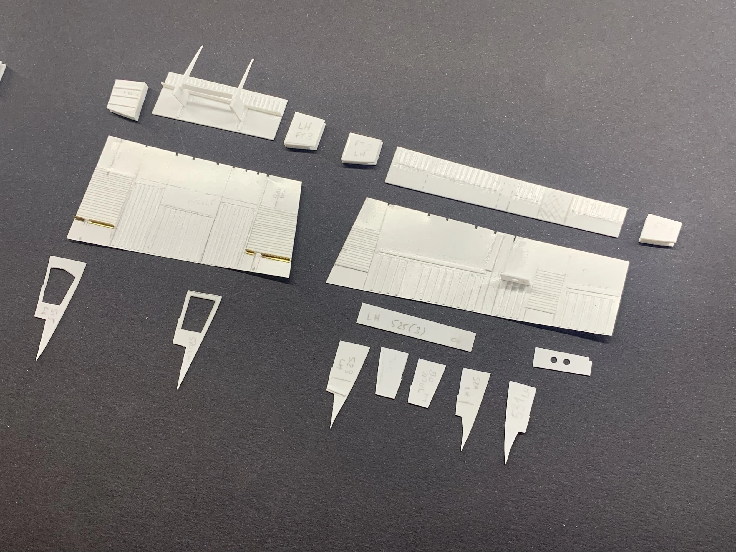
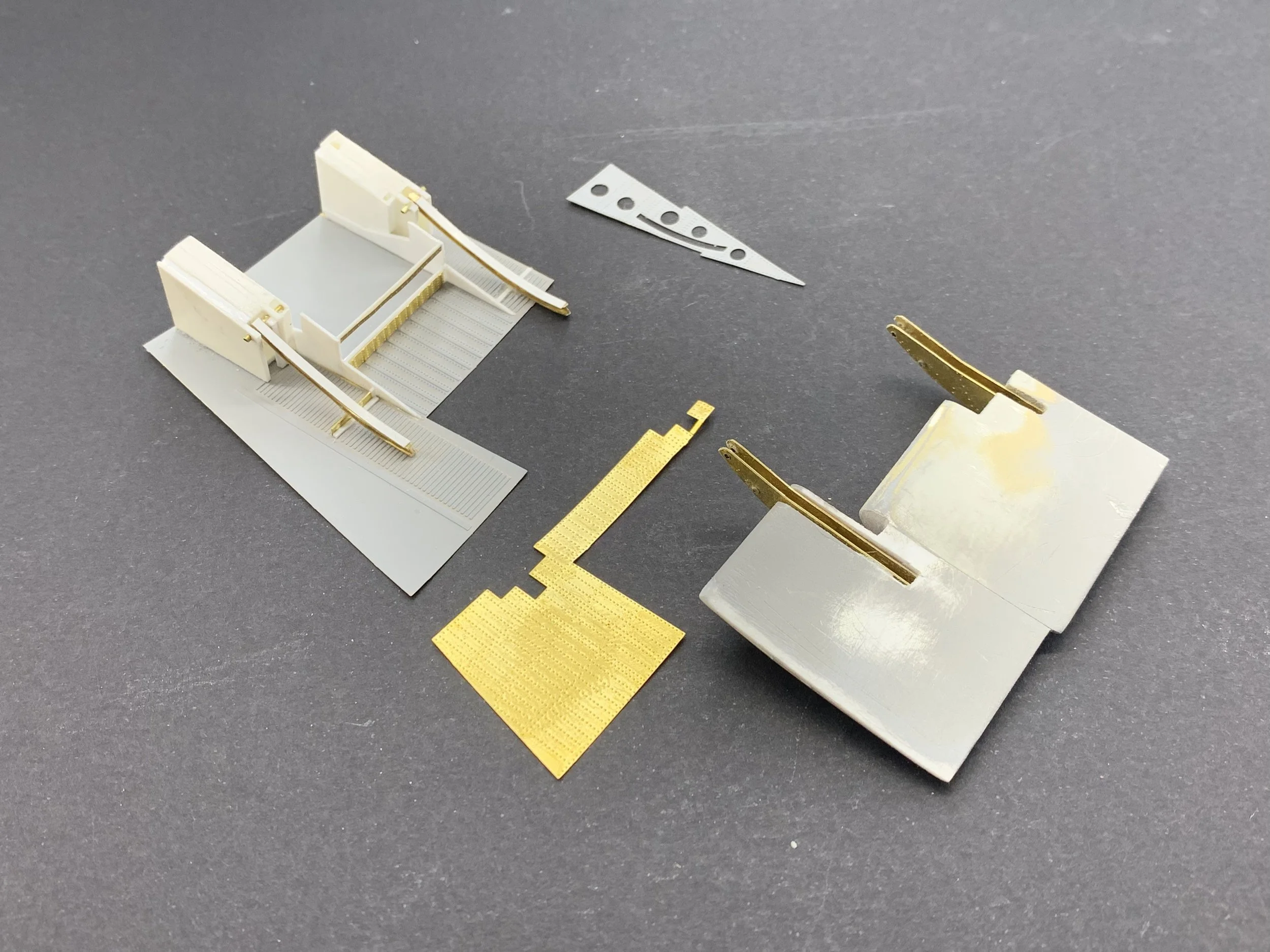
0.25mm Photo-Etched (PE) Brass: Used for the large, flat surfaces to achieve crisp rivet detail that plastic simply can't match at this scale.
Styrene Sheets & Evergreen Strips: Reserved for the structural members. Plastic offers a level of flexibility and "sand-ability" that brass doesn't. It allowed me to make the micro-adjustments necessary when the theoretical design met the physical wing.
Designing for photo-etching brings a specific kind of pressure: once the metal is etched, there is no turning back. To mitigate this, I utilised a "paper-prototype" phase. I continuously printed my 2D designs onto A4 paper, cutting them out and test-fitting them into the wing bays. This iterative process was the only way to ensure that the jump from 2D design to 3D reality didn't result in a bucket of expensive scrap metal.
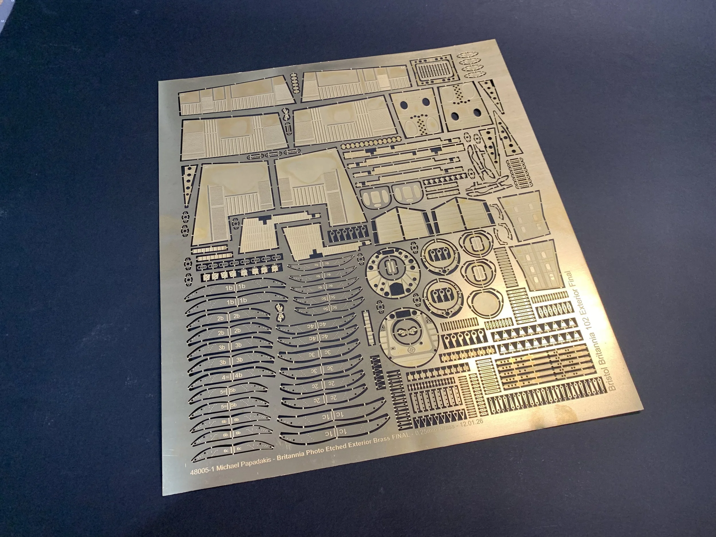
The "Precious" Metal Arrives: Populating the Flap Bays
There is a specific kind of Christmas-morning excitement when the custom photo-etched (PE) frets finally arrive. Holding those thin, crisp sheets of brass represents months of research and digital drafting—but the real challenge begins when "theory" meets the actual plastic of the wing.
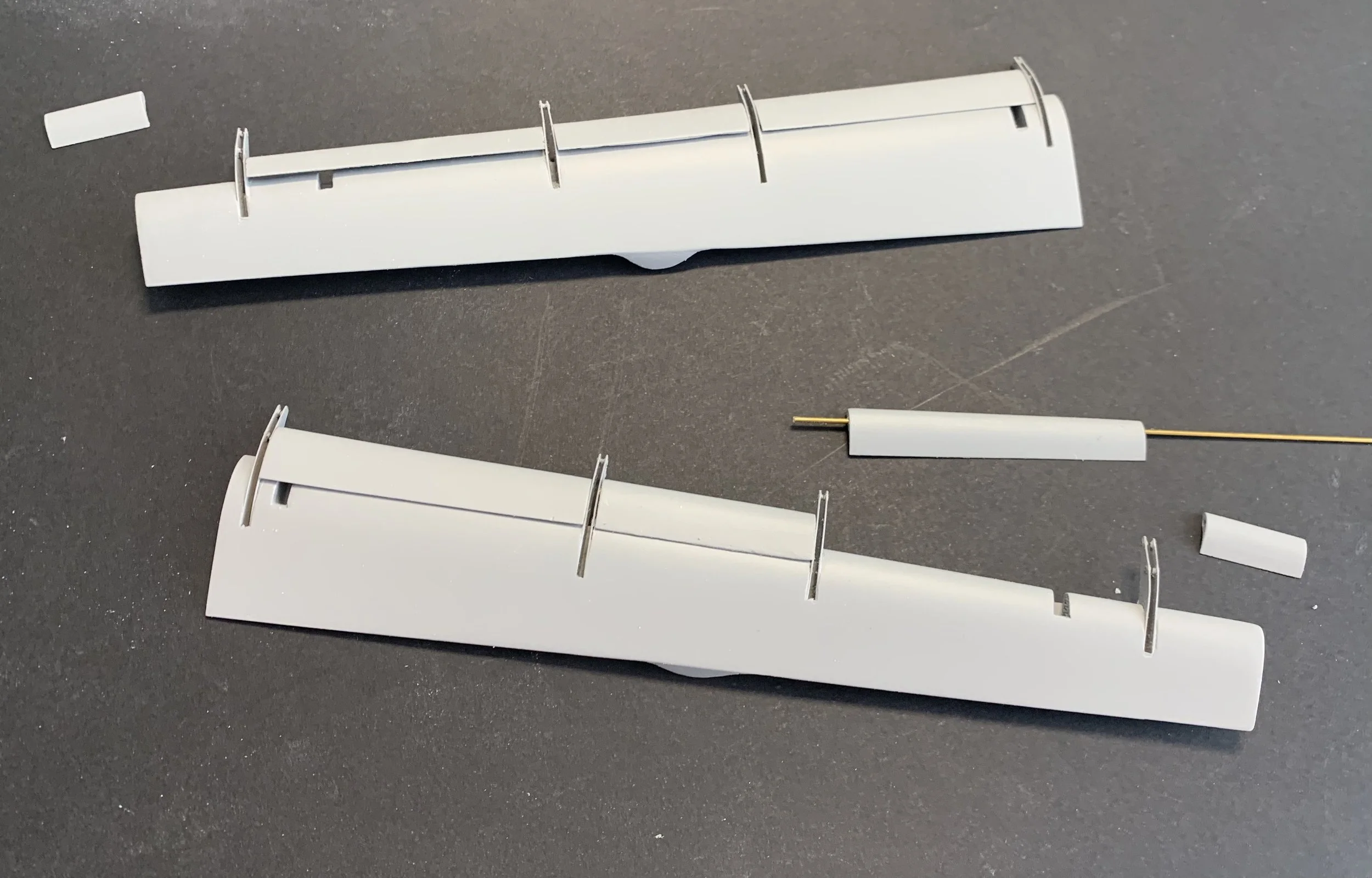
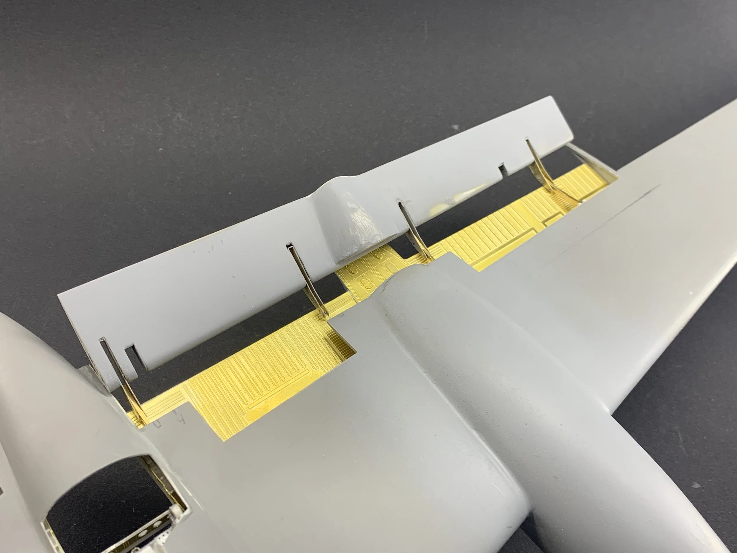
The most critical part of the internal assembly was the installation of the flap tracks. For these, I turned to Albion Alloys 1×2mm (IB2) brass “I” beams. These provide the necessary structural strength to support the weight of the lowered flaps, but they aren't exactly "plug and play." To achieve the correct curve for the tracks, I used a time-honoured workshop technique: I carefully formed the brass beams against the radius of a spray paint rattle can. As any modeler who has worked with structural brass knows, bending an "I" beam is a recipe for distortion. The flanges tend to buckle or twist under the stress of the curve. While the mechanical strength remained, the visual finish was compromised.
To remedy this, I employed yet another hybrid solution:
The Core: The curved brass remains as the structural "spine" of the track.
The Finish: I "skinned" the visible lower sections of the tracks with thin Evergreen styrene.
This gave me the best of both worlds: the rigid support of the metal and the clean, uniform appearance of plastic. It’s a perfect example of how scratch-building often requires a "Plan B" the moment your materials decide to fight back.
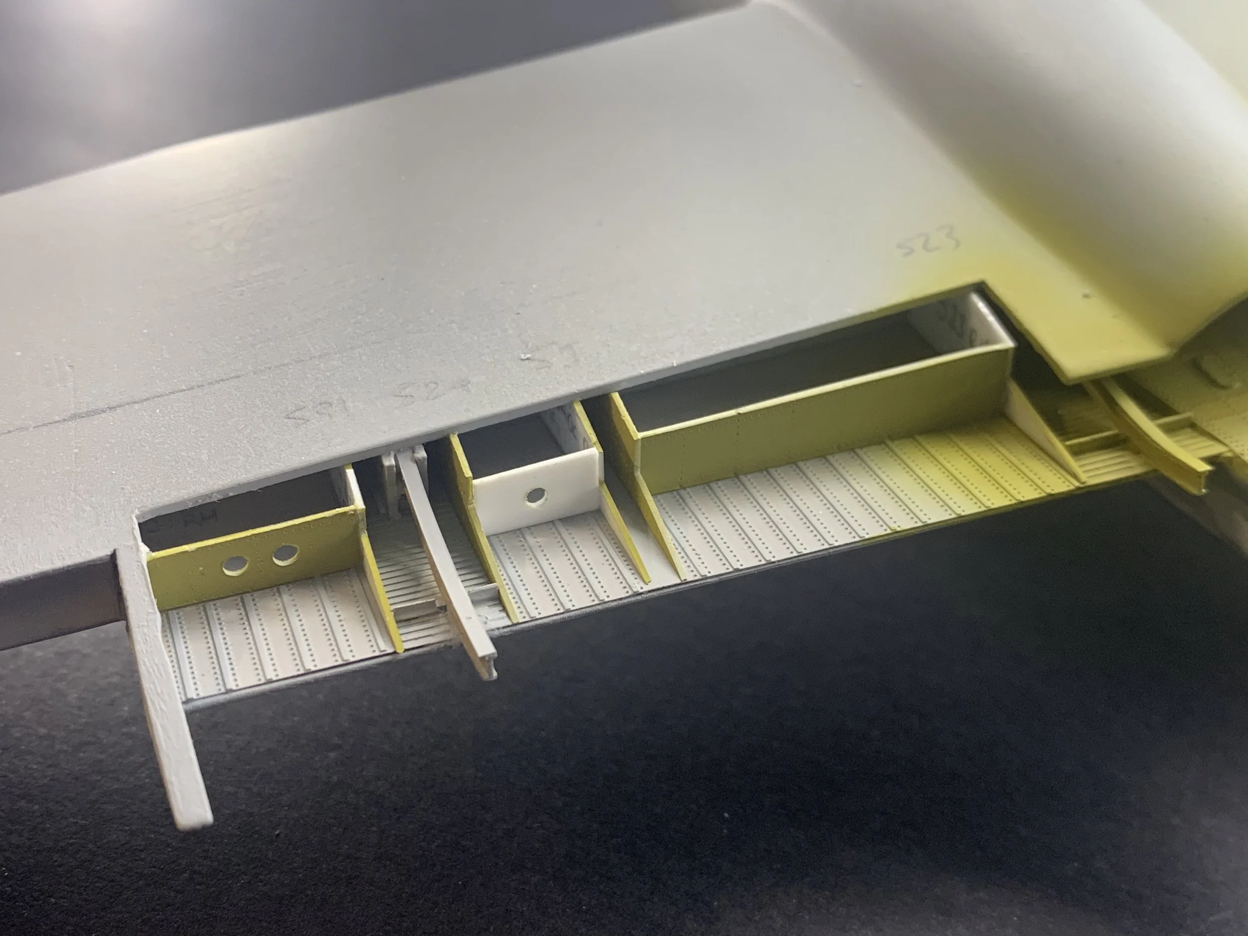
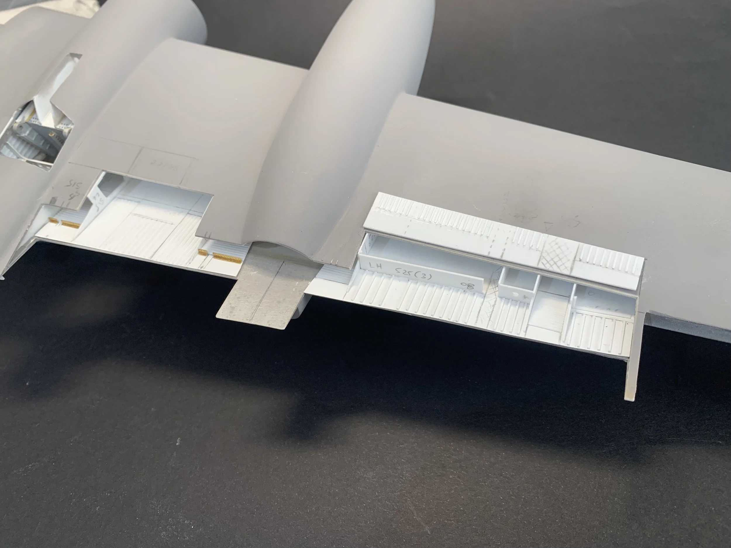
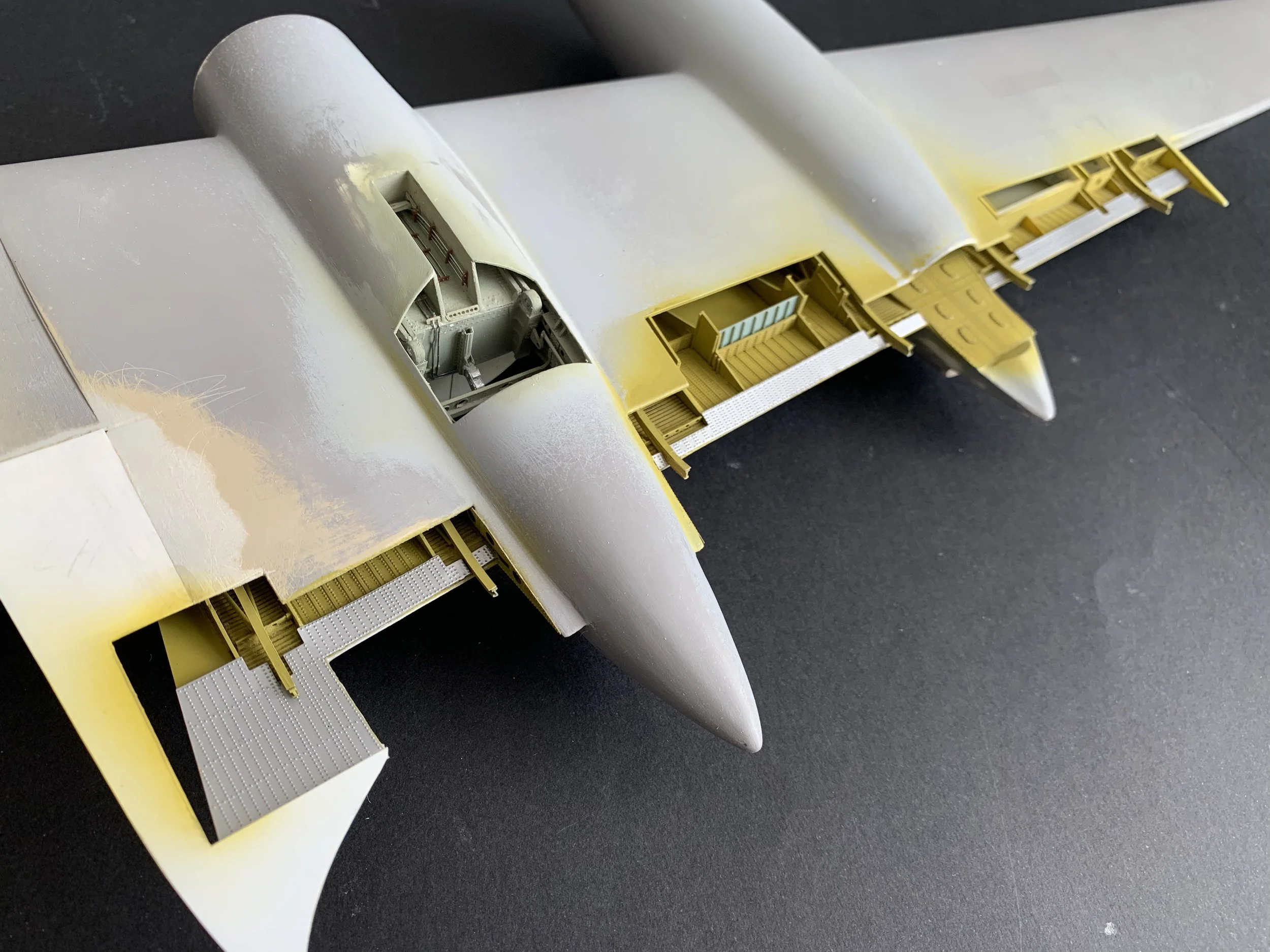
With the majority of components in place, I installed the dinghy housing structure and painted all interior surfaces with Zinc Chromate Yellow and Alclad Aluminium. I then installed the aft sections I had removed for access and filled with Milliput epoxy and coated with Mr. Surface Primer.
The Flap Assembly: A Multimodal Engineering Challenge
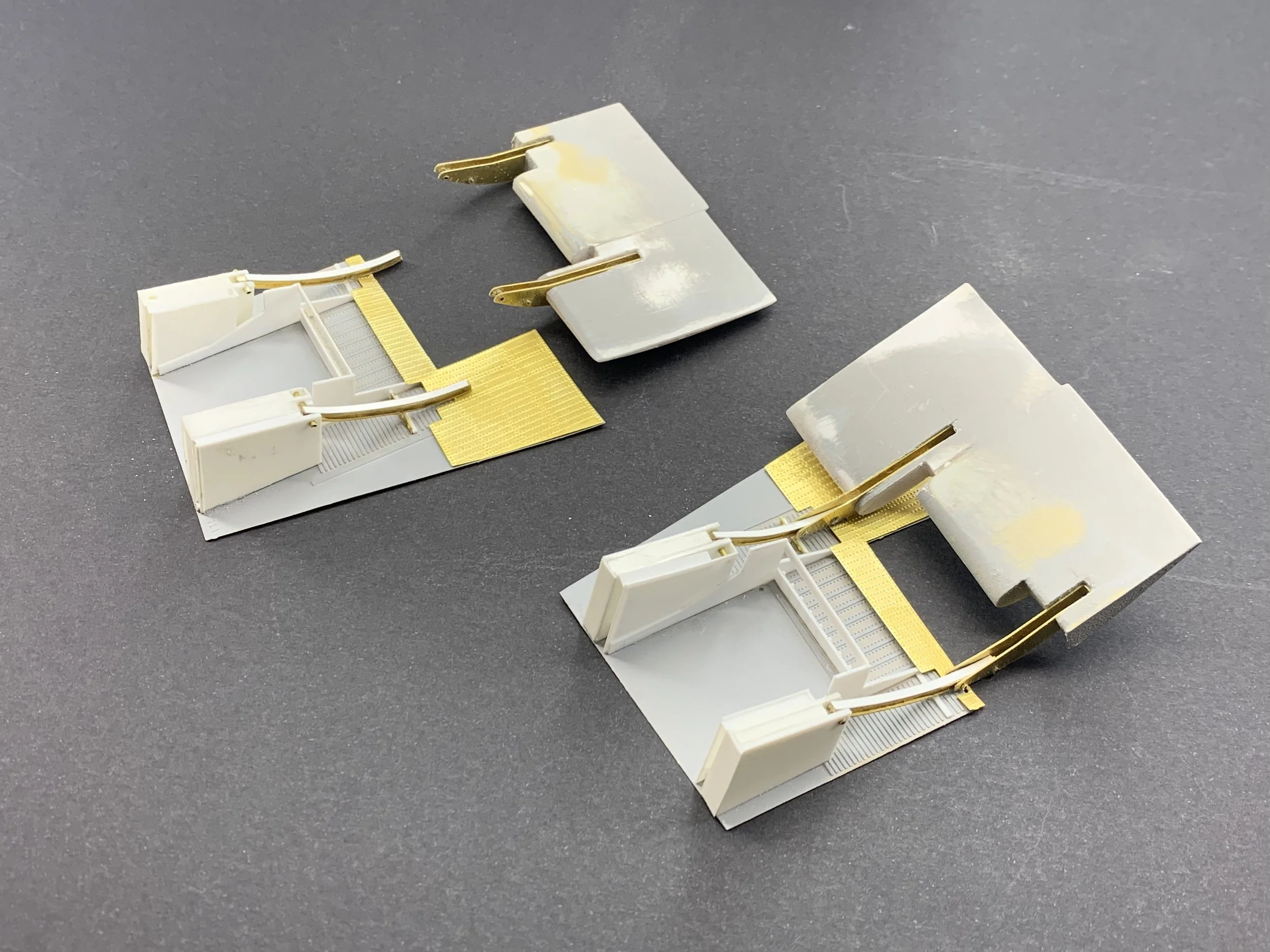
To ensure a perfect fit, the flaps were built in unison with the housing structure and the flap tracks. This assembly required a tri-material approach to balance detail with durability:
The Core: 3D-printed ABS was chosen for its rigidity and resistance to warping. However, I quickly encountered a structural hurdle: the flaps tended to snap along the printed layers under tension.
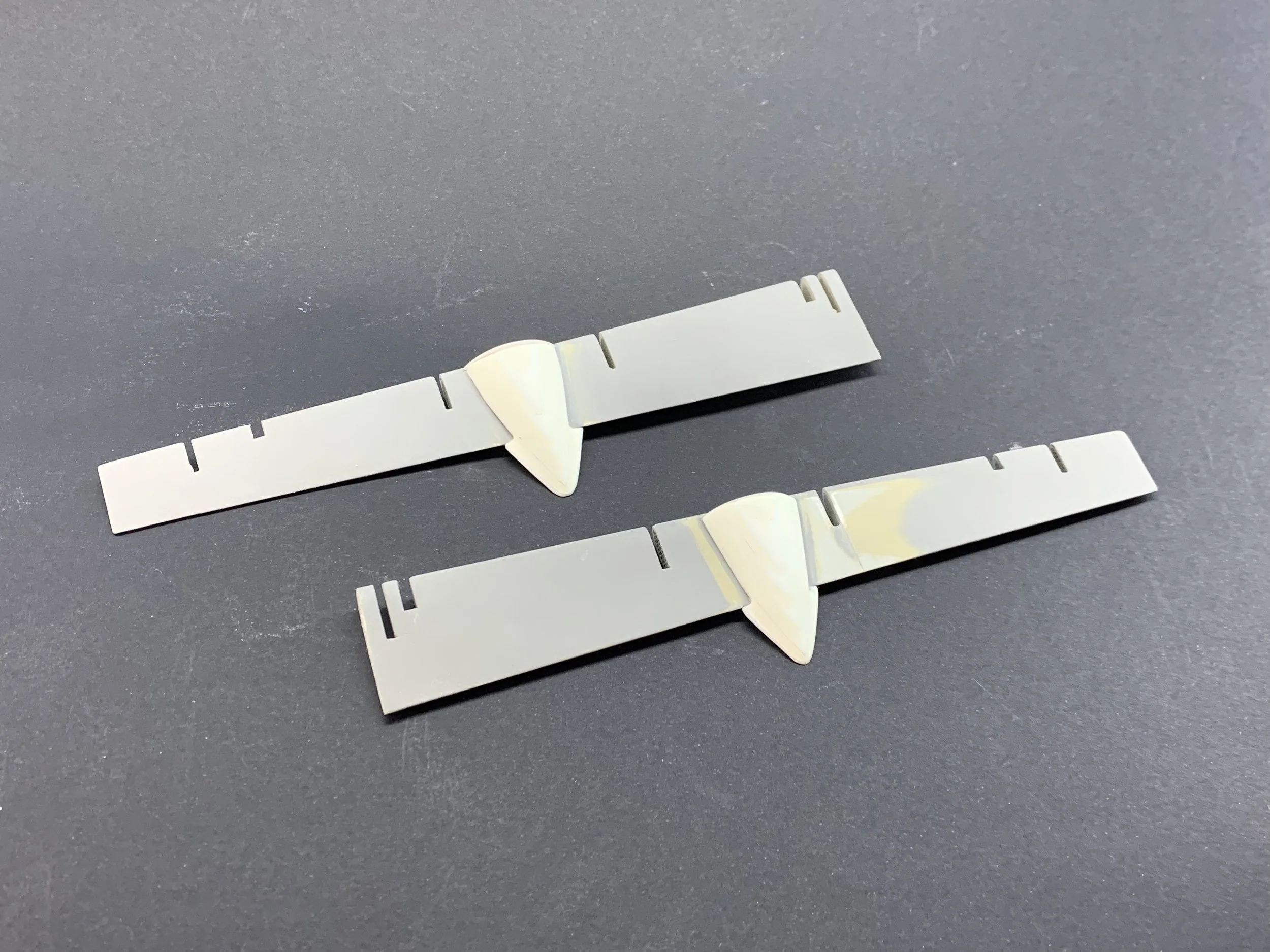
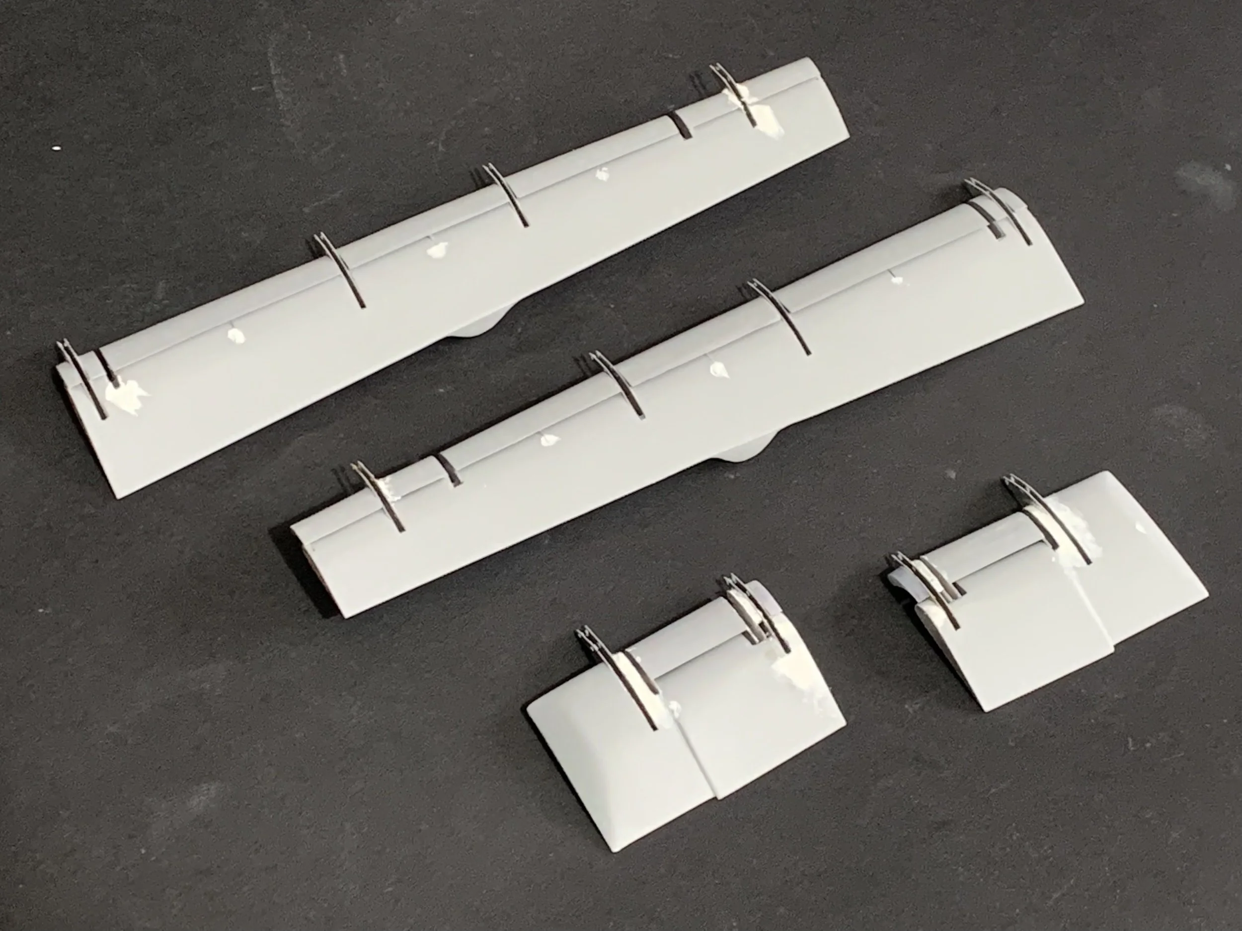
The Leading Edge Slots: 3D-printed Resin was used to capture the intricate, razor-sharp aerodynamic profiles that define the Britannia’s wing.
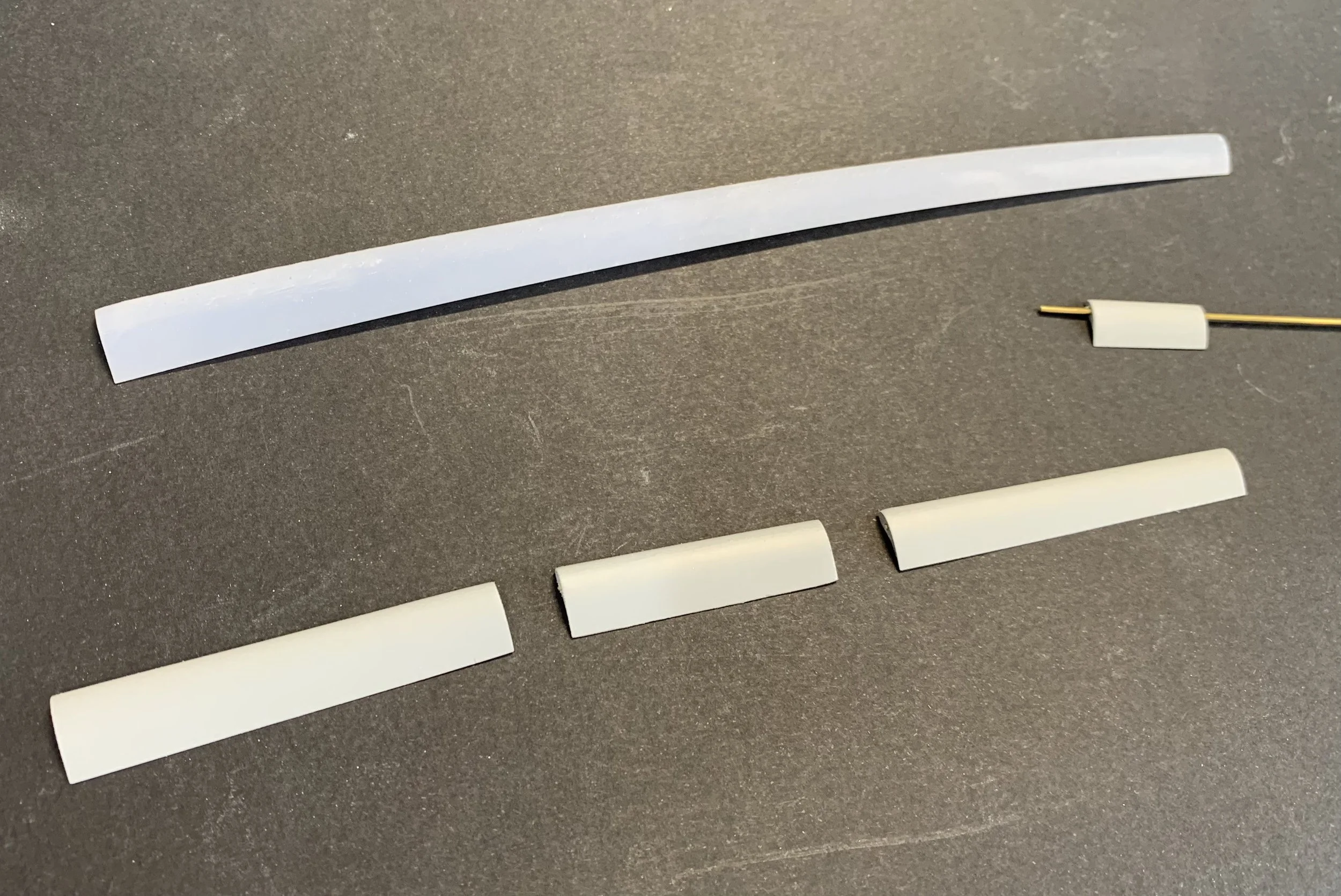
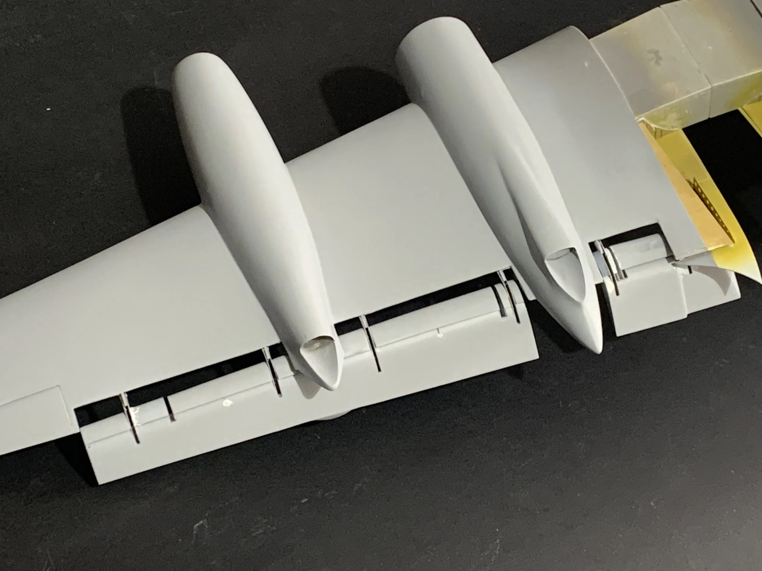
The Bullet Fairings section on the flaps: These were hand-formed using a combination of styrene and Milliput epoxy for a seamless, organic transition.
For the leading-edge airfoil, I initially used a single-piece resin print. Unfortunately, the resin began to warp over time, forcing a redesign. I modified the airfoil to accommodate a longitudinal metal rod; this internal spine acting as a permanent counter-measure, ensuring the flaps remain perfectly straight for years to come.
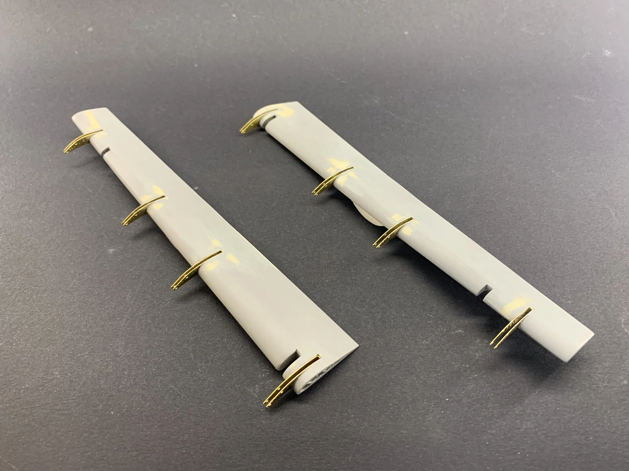
The connectivity between the wing and the flap had to be functional in design, even if not intended for constant movement. I engineered the flap supports in photo-etched brass, specifically designed to slide precisely along the previously installed brass "I" beam tracks.
The final stage of the sub-assembly required a bit of "precision surgery." I cut the specific sections for the flap jacks (the flap actuators) and gradually integrated the resin leading-edge slots into their final positions. Seeing the components finally "dock" into the wing tracks was the moment the "conundrum" finally felt like a solved equation.