The Wisdom of the Wrong Way: Lessons in Shaping the Britannia's Engine Nacelles
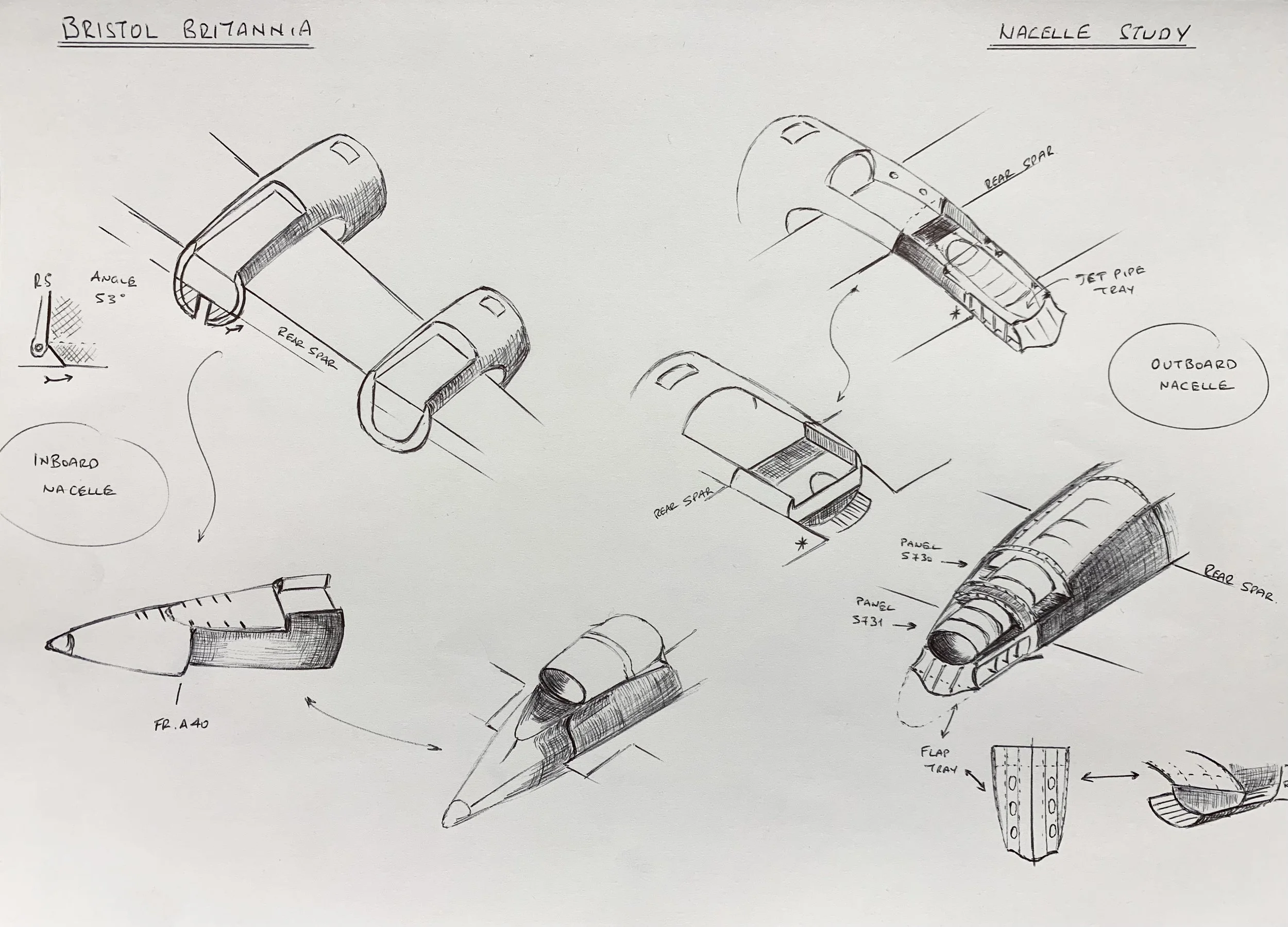
The engine nacelles for the model Britannia are of hybrid construction. Given the constraints of my 3D design abilities and the necessity of maintaining control over consecutive construction steps, I opted for a combination of techniques and materials. I began by consulting historical and contemporary photographs and sketching the components to visualize the intended structure more clearly.
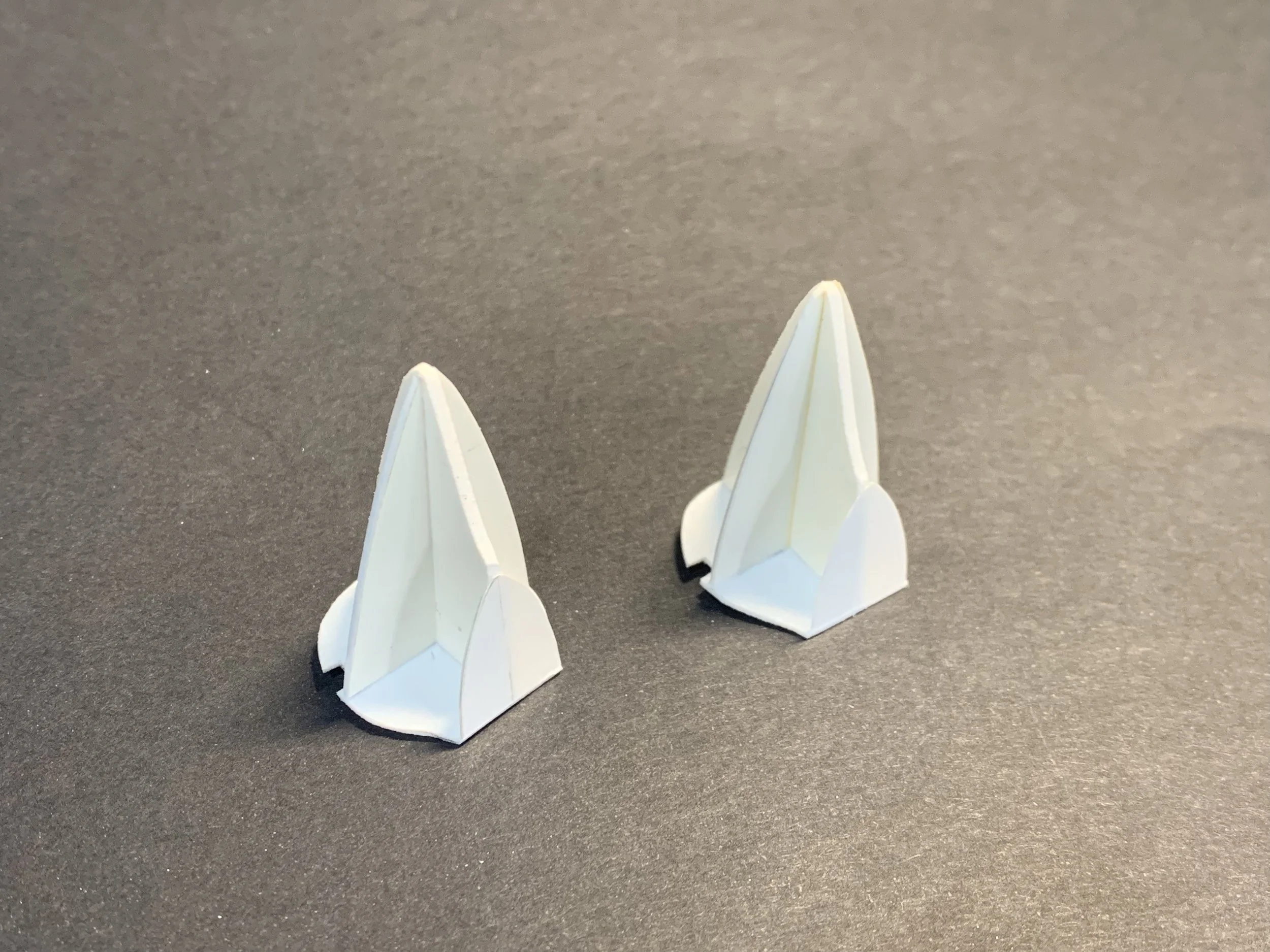
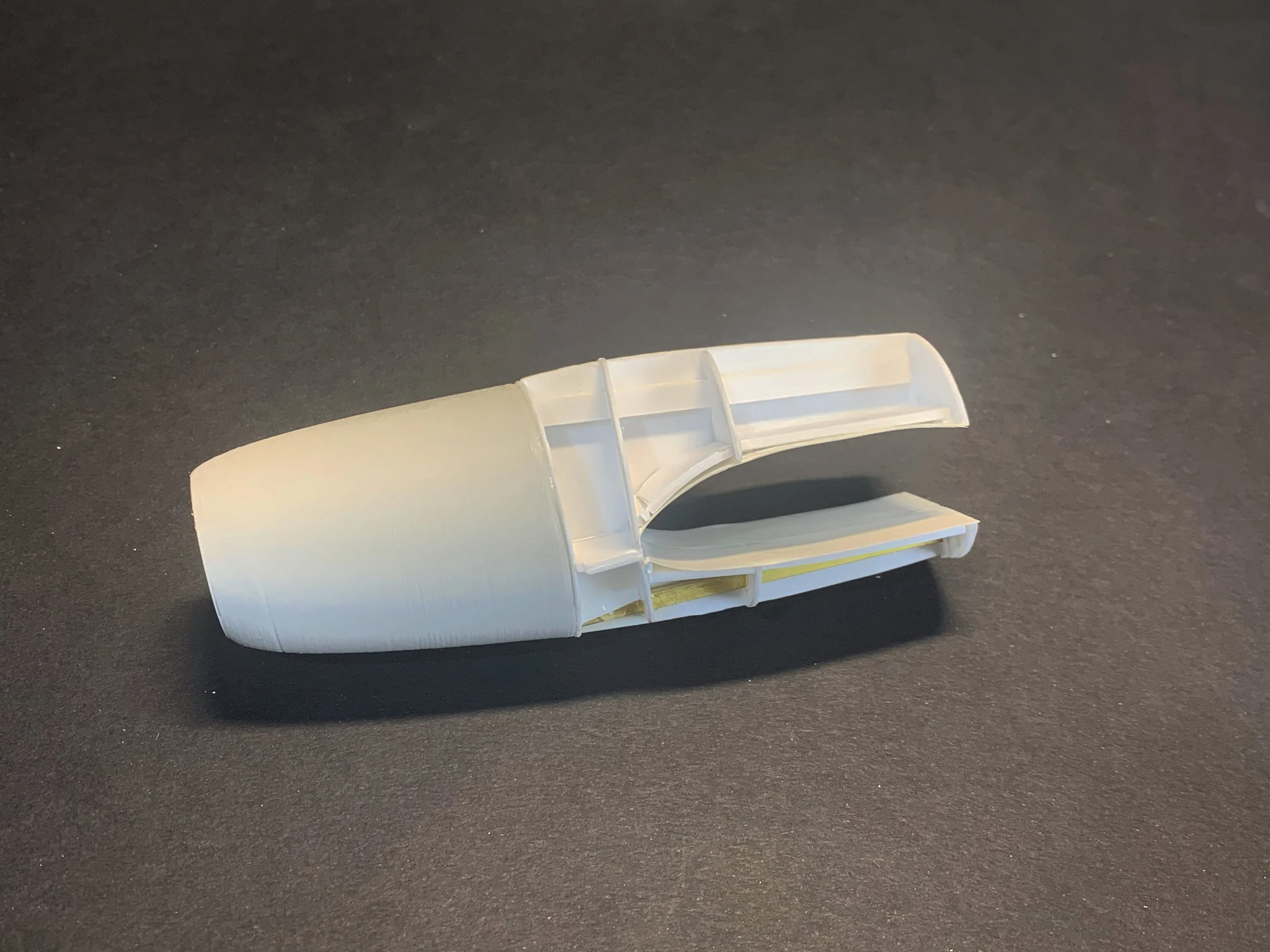
For the engine cowls, I chose 3D-printed ABS plastic primarily for the symmetrical precision that the process would provide. I then designed the mid-section of the nacelles using the 2D software, Affinity Designer, and began experimenting with the physical setup.
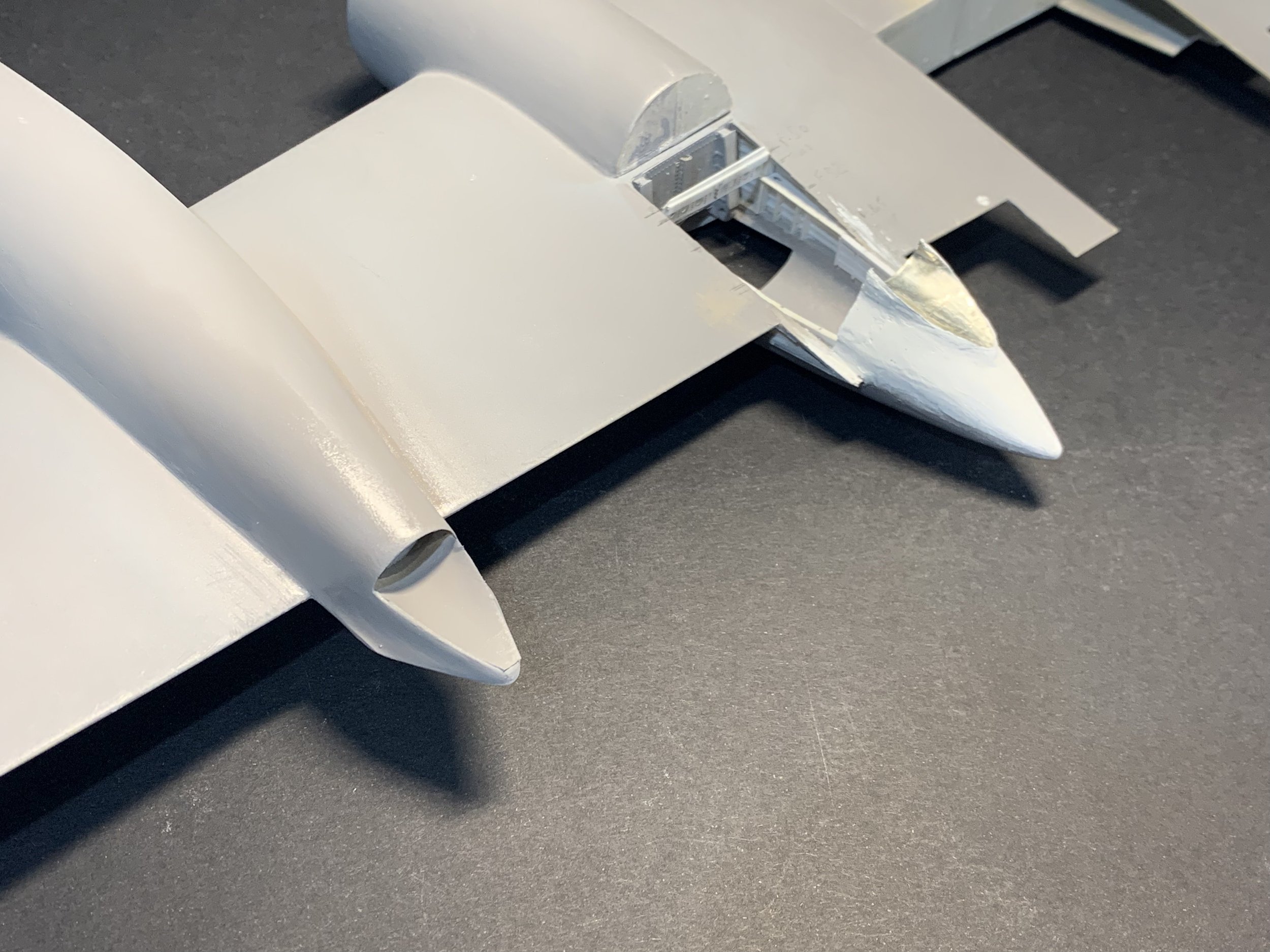
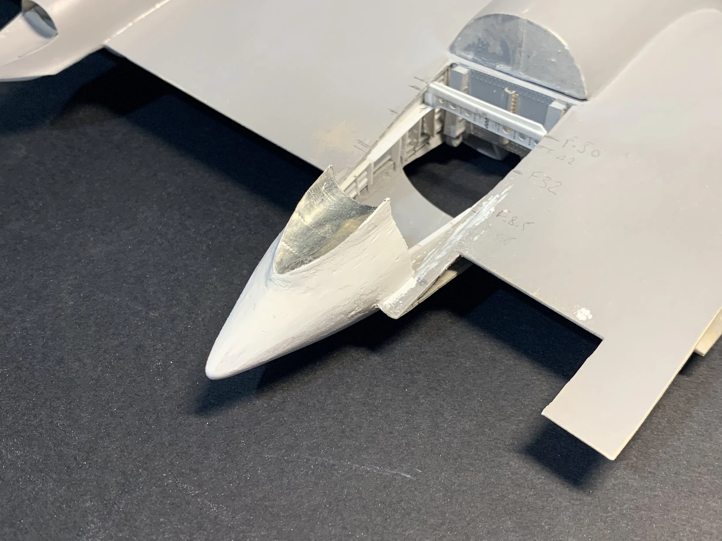
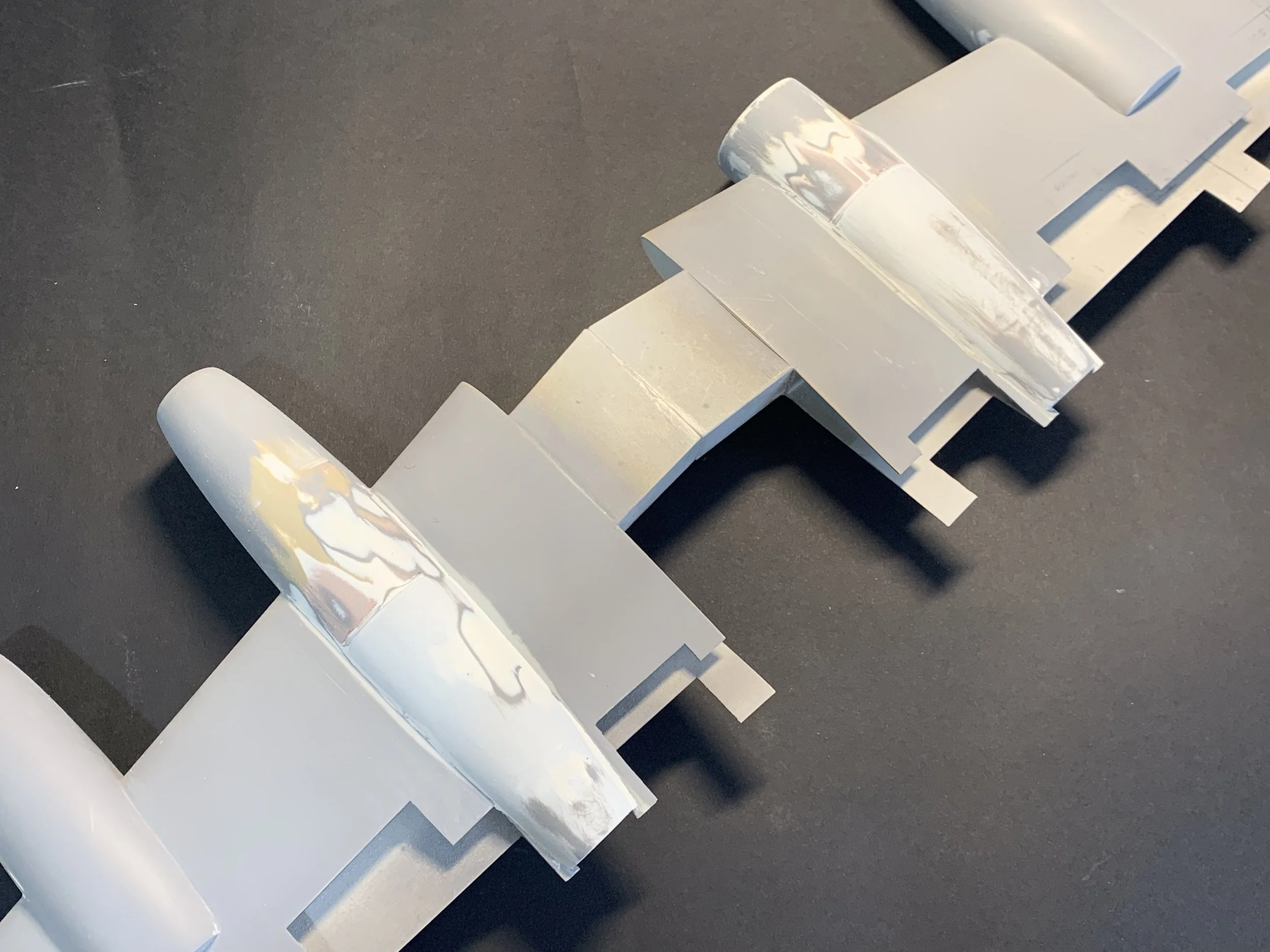
Note the cut-out at the rearmost section of the outboard nacelle that combines the exhaust and the opening for the outboard flap housing.

Prototype 1: Flexibility Issues
The first prototype involved cutting the profiles and selected frames by hand to form the basic framework. Once I began to fill the gaps with Polyurethane (PU) model board, it quickly became clear that this framework was too flexible. The resulting distortion compromised the intended shape when the model board was installed.
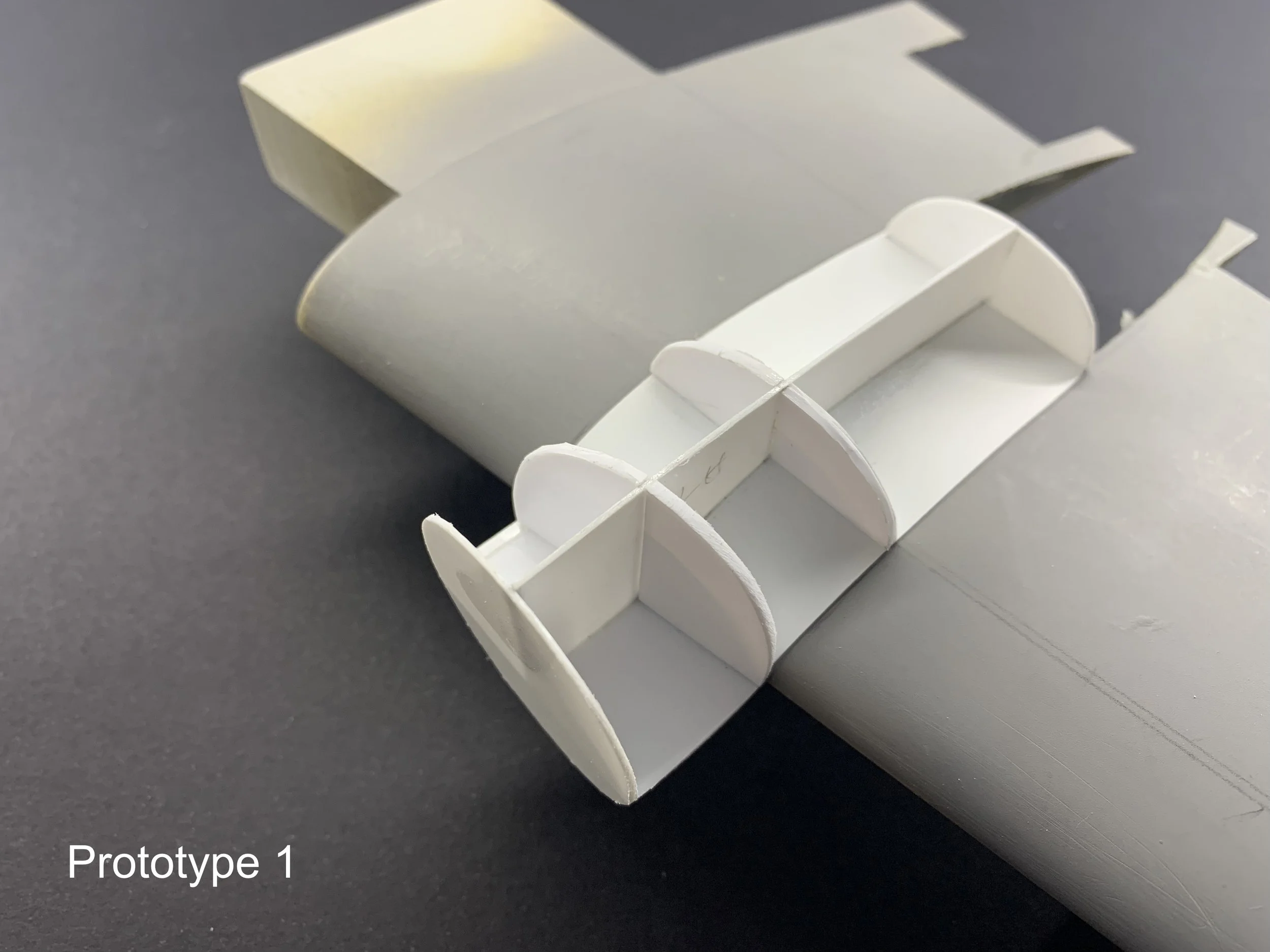
The profile section I used for this prototype was too thin causing distortions after the installation of PU model board.
Prototype 2: The Alignment Snag
The second version was more meticulously designed, with the components cut by my reliable Cricut Maker. This time, I opted for 0.75mm styrene plastic, which the machine was set to scribe rather than cut. I doubled up on the 0.75mm plastic for critical sections like the main profile and decided to embed a metal bar along the side to reduce the plastic's tendency to warp after the model board was installed.
Despite this careful planning, the problem arose in a different area: the wing contour. This resulted in a slight misalignment, causing the inboard nacelles to have a two-millimeter difference between the firewall and the wing's leading edge. In this case, my overconfidence and hastiness were to blame, as I had assumed the careful preparation of the parts was sufficient.


The Final Version: Structure and Material
Yet again, I chose to start over, this time with a strengthened assembly and an entirely different approach. I decided to permanently attach the power plant to the mid-section framework first, ensuring the entire unit was perfectly perpendicular to the aircraft's lateral axis before installing the model board pieces.
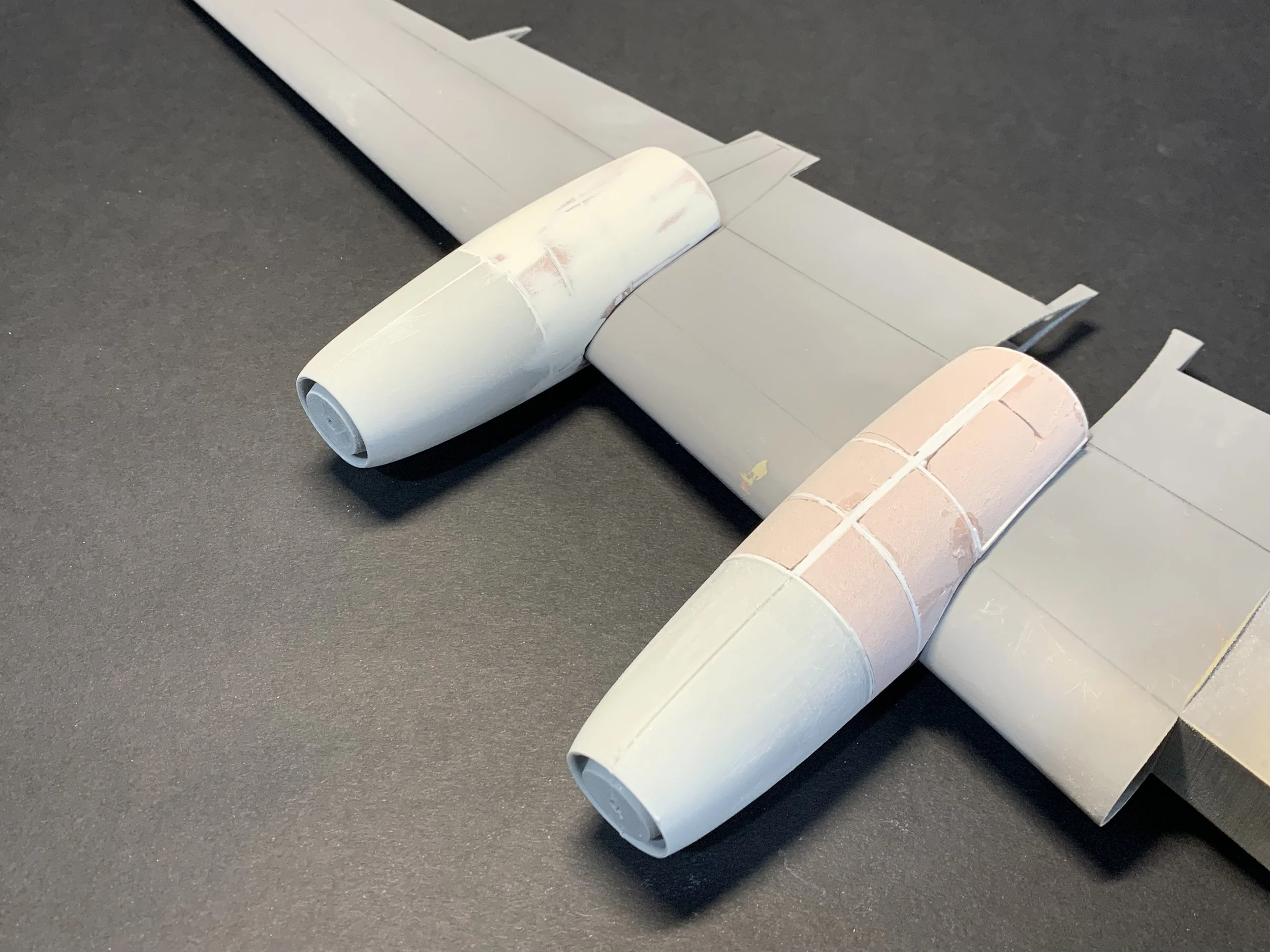
As my supply of medium-density model board was running low, I ordered a high-density model board instead. While this new material proved more difficult to cut with a saw, it was significantly superior when sanding it to the desired shape. Crucially, I made sure to take my time, verifying that the shape of each nacelle remained straight after every consecutive step of the model board installation. The high-density board had the added benefit of requiring very little, if any, body filler to achieve the final contour, allowing me to move straight to Milliput Superfine for the first coat of surface filler. I also opted to construct all four nacelles in one go rather than doing the outboard ones first and then the inboard ones.


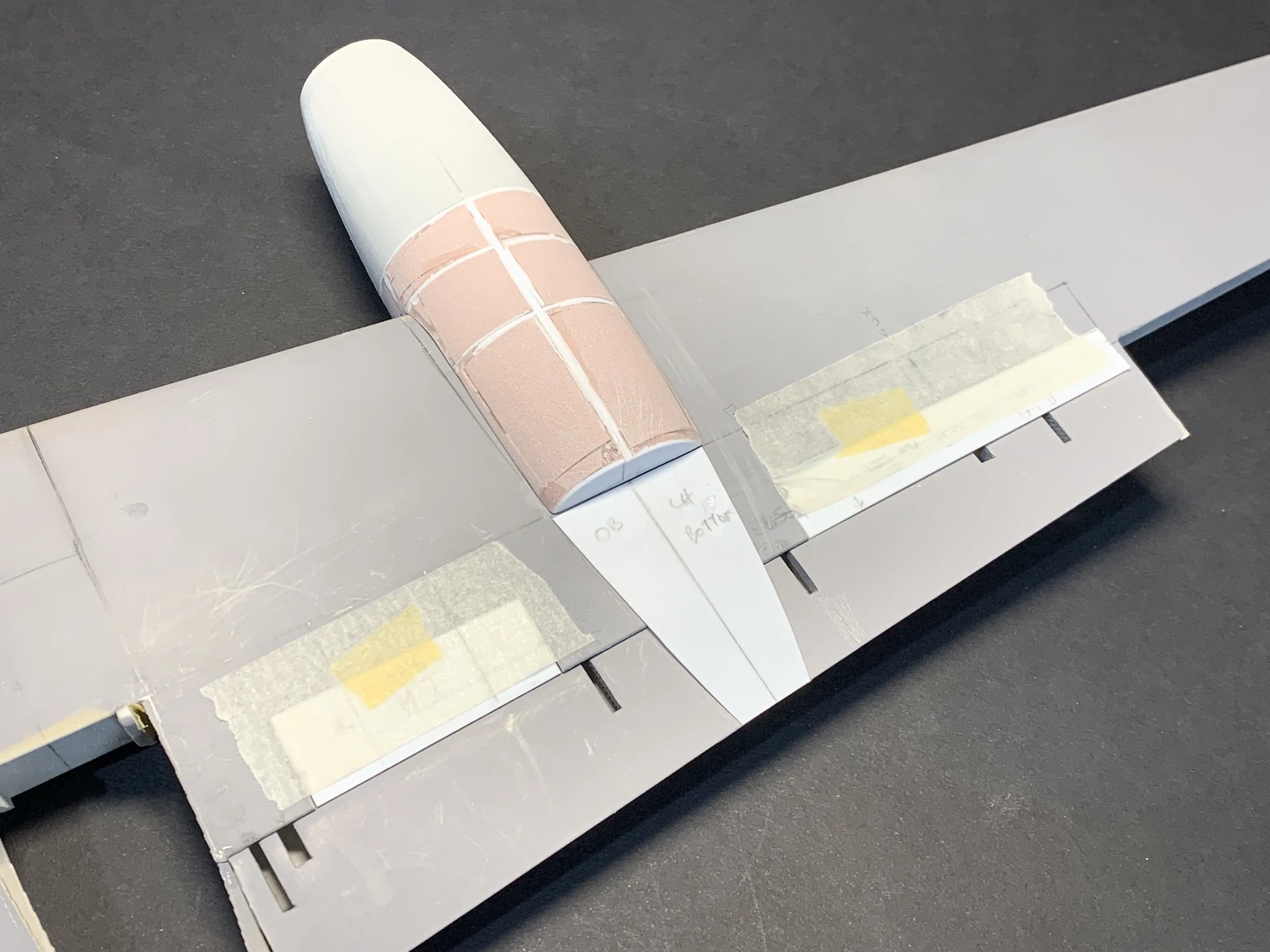
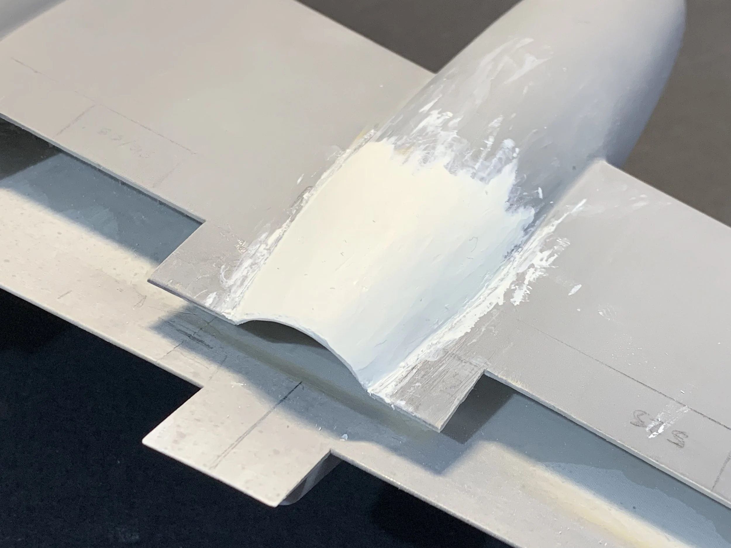
Nacelle Alignment
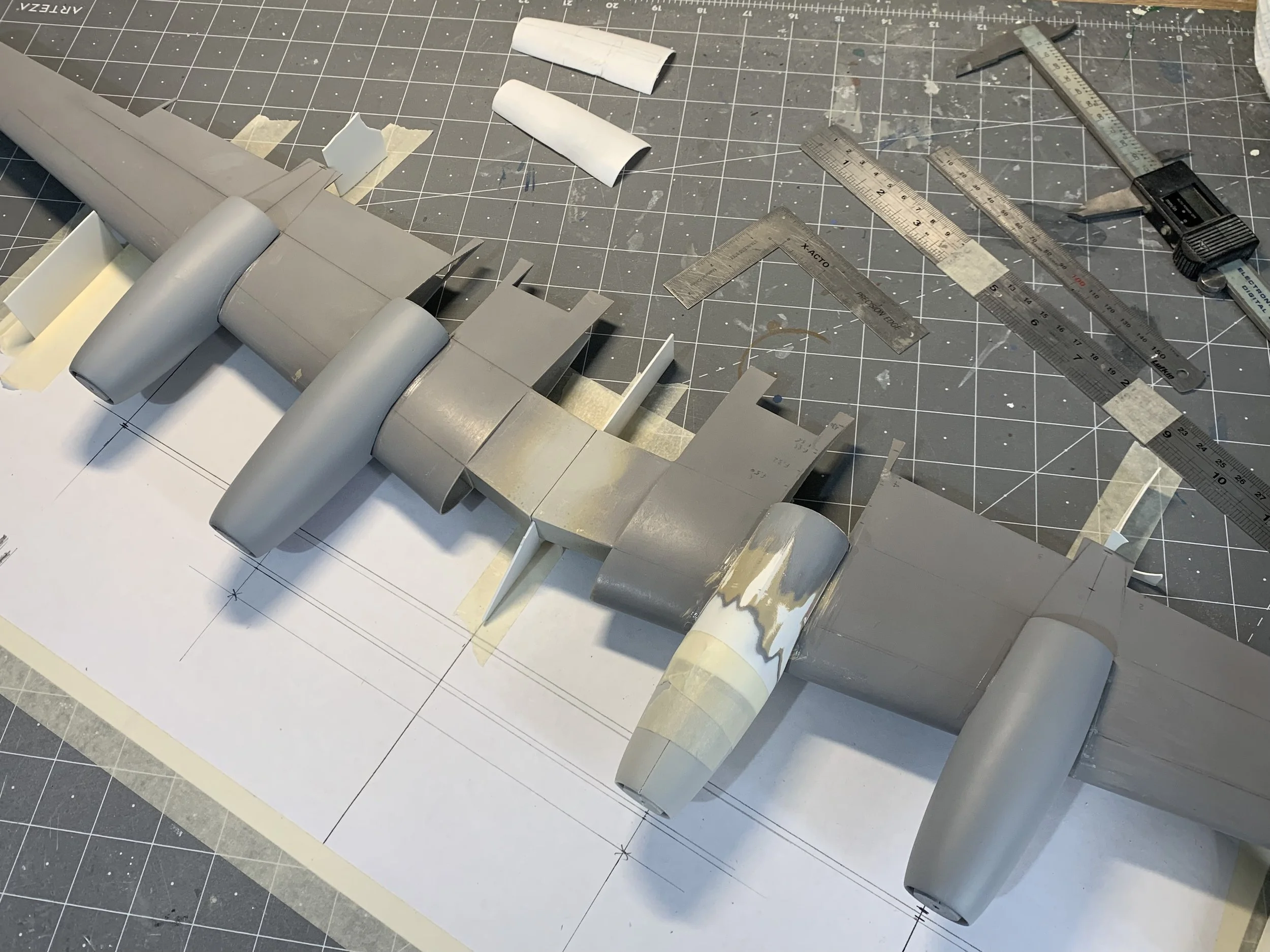
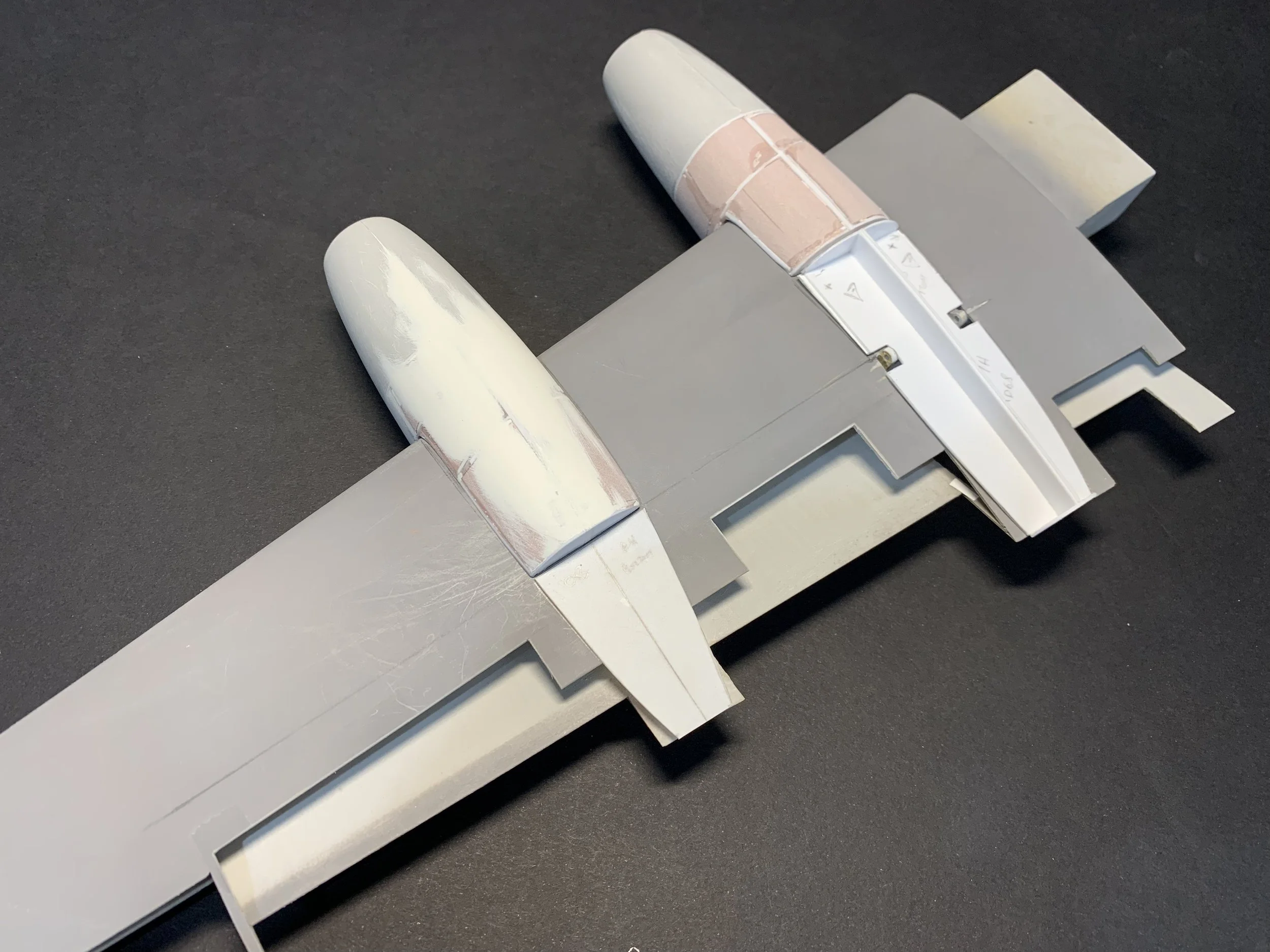
A vital part of the model’s construction is the alignment of the engine nacelles. Despite the efforts described above for the best possible fit on the wing contour some fine tuning was still required to ensure all four nacelles were parallel to the longitudinal axis of the aircraft as well as at equal distances from the “ground”. A very simple jic was designed on a couple of A4 sheets and the wing was secured onto the workbench to minimise movement. Due to the sheer size of the wing I had to set my jig at the angle seen below so it would fit on the cutting mat. To facilitate No.2 engine alignment, the forward nacelle was temporarily attached to the location of the fireproof bulkhead.
Undersides
With the majority of work completed on the upper side of the wing I shifted my attention to the undersides. I vacuum formed the inboard nacelle landing gear bay as well as the aft portion of the outboard nacelles which housed the flap fairings. The techniques and materials remained consistent with the rest of the nacelle construction.
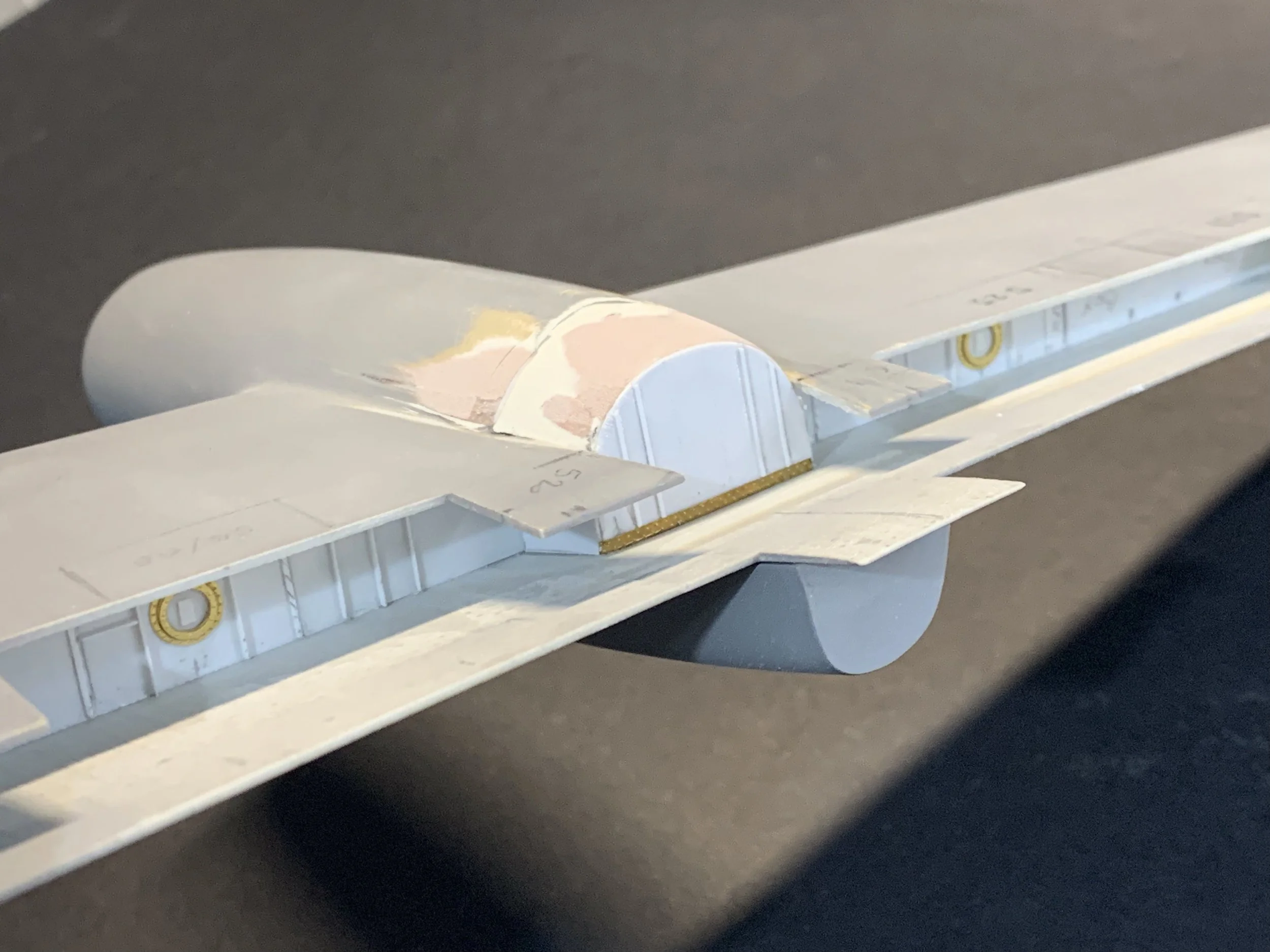
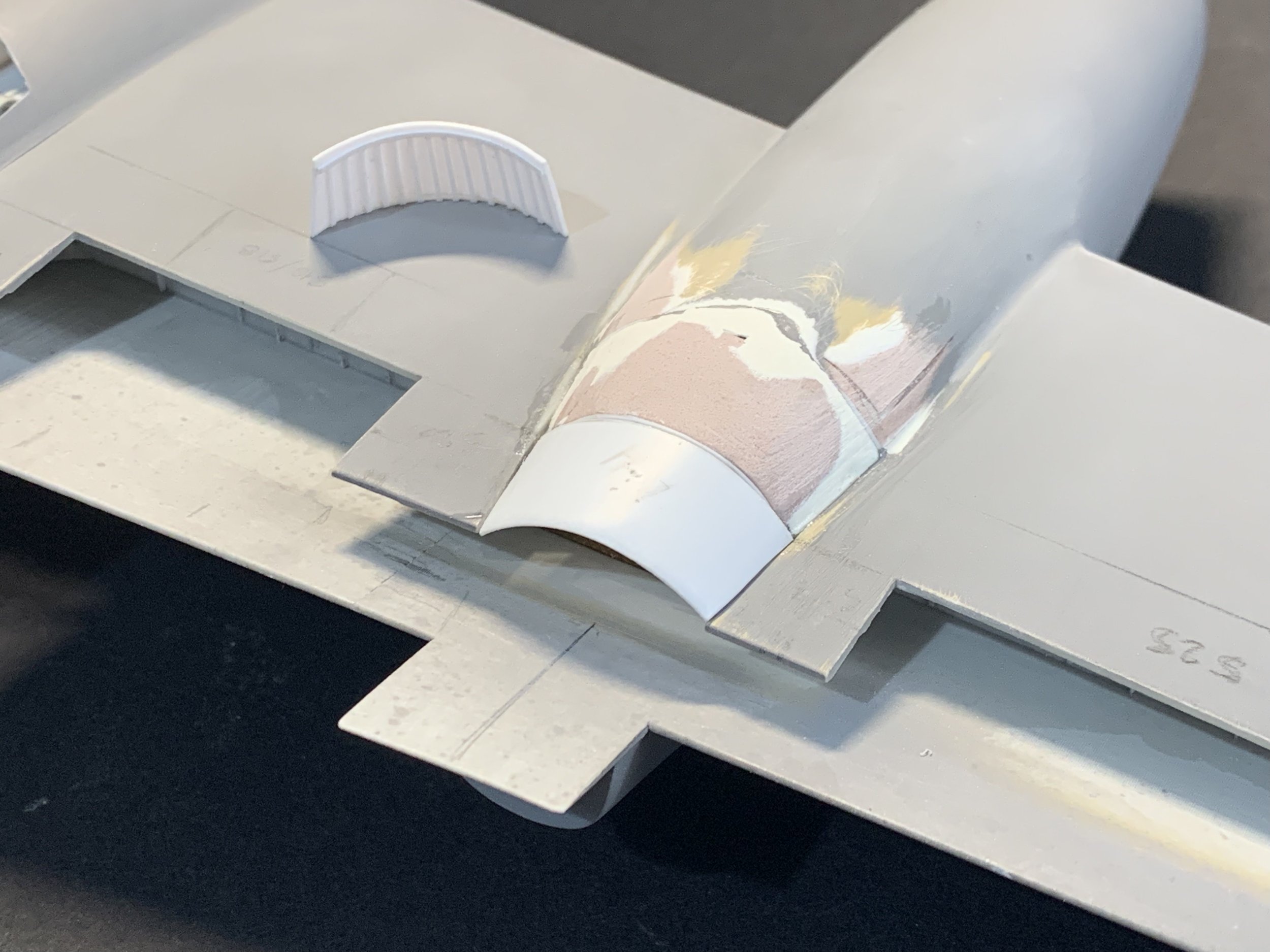
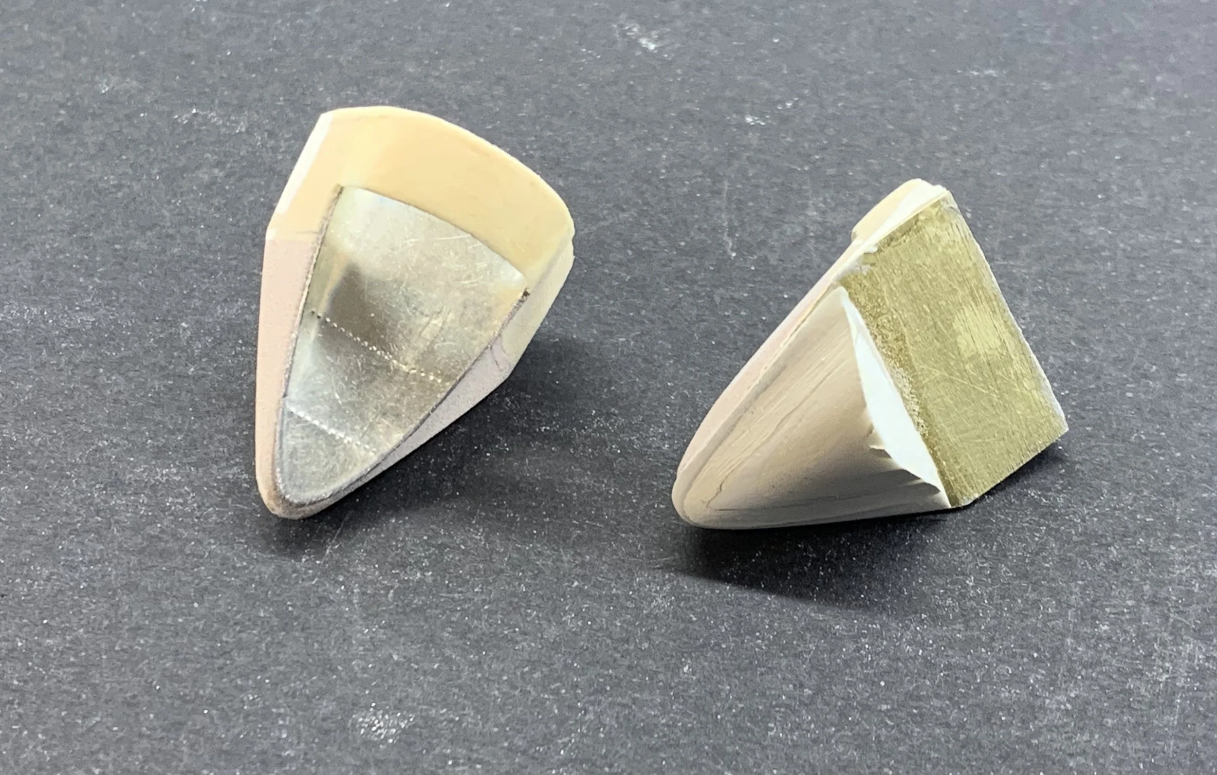
Exhausts
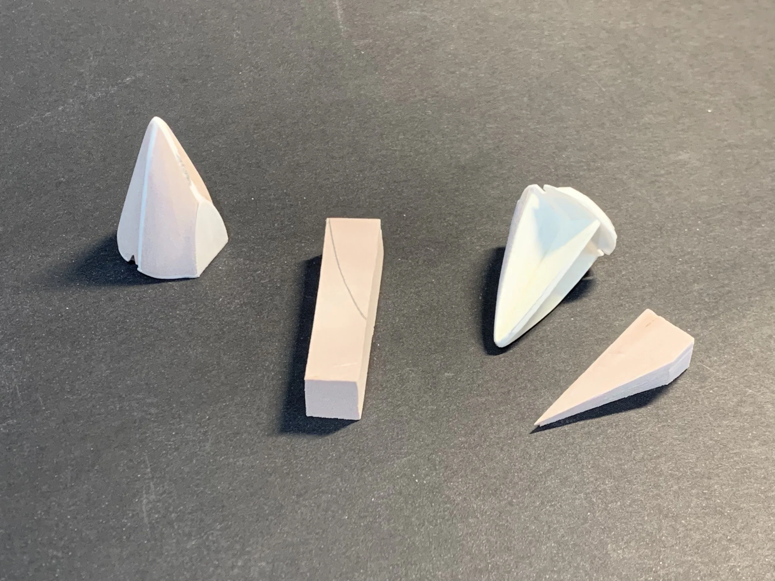
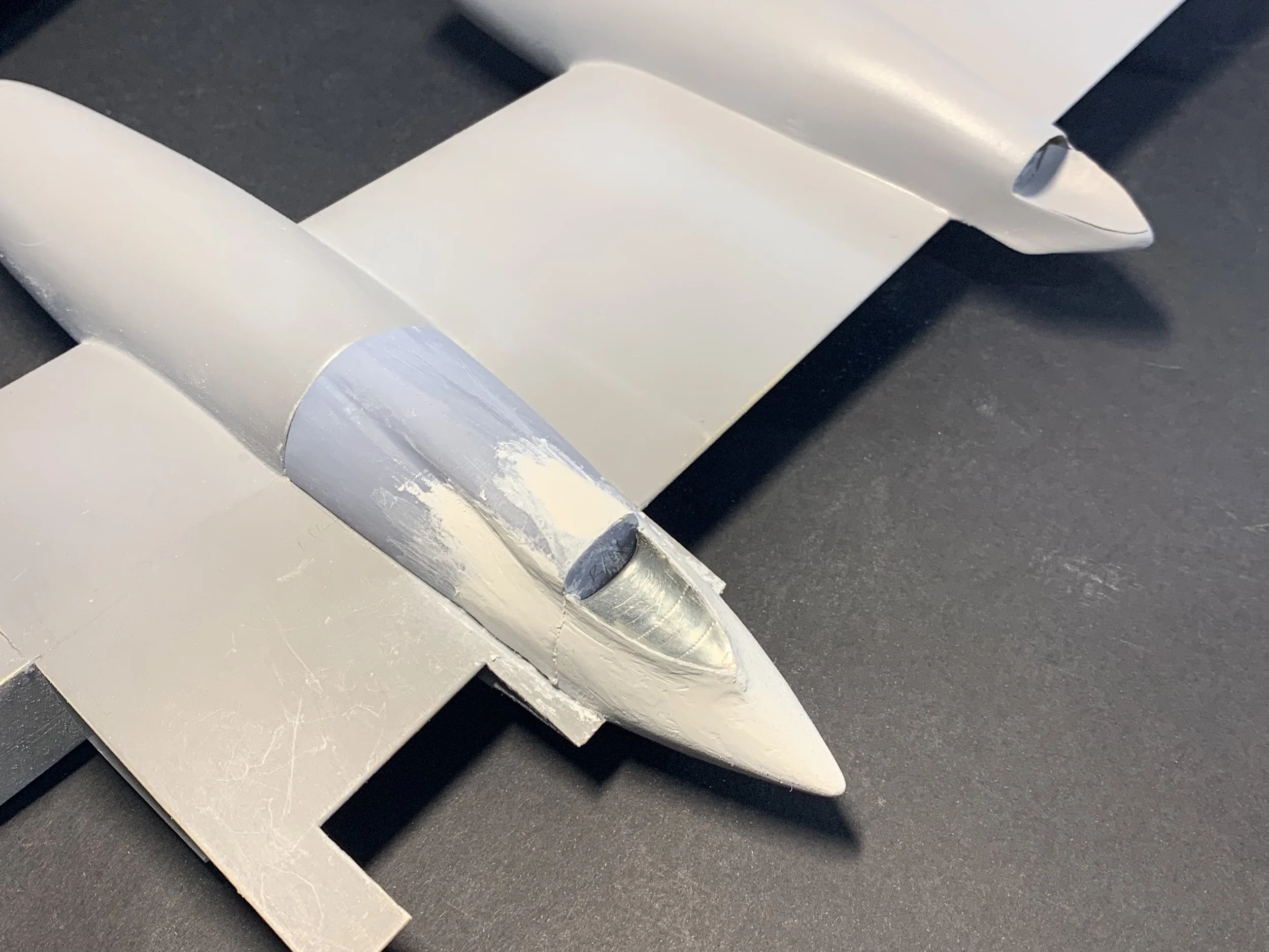
Yet another demanding part of this project was the creation of the engine exhausts. The outboard exhausts were sculpted using high density PU model board and using pewter sheet for the heat shields. To add to the complexity, the rearmost part of the fairing had to correspond to the moveable portion attached on the outboard flaps. The inboard exhausts were crafted around a styrene assembly using a variety of thicknesses depending on the rigidity required for each section using the lessons learned in the first part of this article. Both were subsequently attached in their appropriate locations and covered with Milliput epoxy. The 3D printed resin section above the wheel bay was also treated with Milliput but not attached yet because of the detailing work still required in the landing gear compartment.
Unfortunately, and despite my best intentions, it is very difficult to document on how I got to this end result. Firstly, this a very messy operation with a tremendous amount of dust being created in the process. Additionally, for the duration of this construction, I have to deal with numerous symmetry checks and ensuring that all crafted components seamlessly blend in together so my full attention is constantly required.
A word of advice: You need to be very experienced in using these materials and technics if you are to attempt such an undertaking.